
HartRAO Home > HartRAO 26m Telescope Surface Upgrade 1998 - 2005
The surface of the main parabolic reflector of the 26-m Hartbeesthoek radio telescope comprises 252 panels. The panels installed in the 1968 had 1-cm diameter perforations, which prevented the telescope being used at wavelengths below about 2 cm, or a frequency of 15 GHz. In addition, the rms error over the surface was about 2.5 mm, which similarly prevented useful operation above that limit. A programme to replace the surface panels with solid panels with a lower surface error began in 1998. After two years of developing panel-making techniques, production of new panels got under way in 2000 and installation began in April of that year (~JD2451643). The last panel was installed on 2003 September 10 (JD 2452893).
Alignment of the panels using theodolite and tape measure was initially carried out during the day, culminating in a night alignment session on 2004 September 02-03 (JD 2453250.5). The subreflector was realigned on 2004 October 8-10 (JD 2453288.5). After measurements showed that the subreflector was level east-west to 1mm over its diameter, the four main surface panels over the alignment points were reinstalled on 2004 October 15 (JD 2453294.0).
The upgrades to the telescope have caused its mass distribution to change, and for it to become top heavy. The out-of-balance force was measured in 2005 March. Lead counterweights totalling about three tonnes were manufactured. The first set were installed on 2005 April 14 (day 104, JD 2453475). Welding of cracks in the counterweight structure was carried on 2005 April 21/22 (day 111/112, JD 2453482 / 2453483) and 2005 April 25/26 (day 115/116, JD 2453486 / 2453487). The second set of counterweights were then installed on 2005 May 6 (day 126, JD 2453486).
For calibration of microwave holographic measurements of the surface alignment, four panels were offset vertically from their nominal positions on 2005 July 18 (JD 2453569.8). A ring 1 panel was offset -3 mm, a ring 2 panel by +3 mm, a ring 4 panel by +6 mm and a ring 5 panel by -6 mm.
The rebalancing of the telescope carried out in 2005 April - May meant that the telescope pointing map in use since the early 1990's was significantly in error. Observations of pointing calibrators, initially using the 13cm receiver and then the 3.5cm Dicke-switched system, were applied to the pointing model of W E Himwich, as described in the MKIV VLBI Field System Documentation. The new model was made operational on 2005 September 12 (day 255, JD 2453626.08).
Tests of the aperture efficiency of the telescope at 12.2 GHz after alignment of the surface panels using the theodolite and tape measure indicate that this has improved from 0.22 pre-upgrade to approximately 0.50. This implies that the efficiency is essentially the same in all frequency bands.
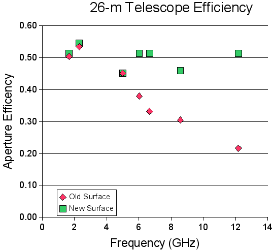
The aperture efficiency was measured by scans through the calibrator sources 3C123 and 3C218 (Ott et al. 1994, Astronomy & Astrophysics, 284, 331). The change in aperture efficiency from before to after the upgrade as a function of frequency is shown above.
The measured efficiency at 8.5 GHz after the upgrade is lower than the maximum possible owing to the relatively large offset of the feed from the axis of the telescope. The 1.6 GHz feed is also far off axis, but in this case the offset was compensated for by tilting the subreflector through half the feed offset angle. However this was not done for the 8.5 GHz data shown in the graph.
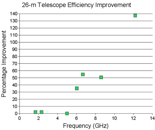
The improvement as a function of frequency is shown above as a percentage.
A typical spectrum of a methanol maser at 12.2 GHz before the upgrade.
A comparable spectrum obtained after the surface upgrade shows the big improvement in signal to noise ratio that the upgrade has brought.
Night surface alignment - 2004 September 02
Last new panel installed - 2003 September 10
Rings 5 and 6 complete - 2002 October 15
Rings 3 and 4 complete - 2001 October 15
Ring 2 complete - 2001 March 30.
The new antenna surface panels were being built onto the backing frames of the old panels removed from the telescope, with extra ribs to provide greater rigidity. The mean surface tolerance of the individual new panels averages under 100 microns, which is well within specification. The production rate of panels was typically six every ten days.
Steps in the production process are illustrated below.
Click on the images for more detailed views.
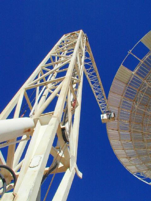
The Hi-ranger, or "cherrypicker", is seen in action above as Simon Morake and Amos Kekae undo the bolts holding a set of panels onto the telescope support structure. They are working about 25 metres above the ground.
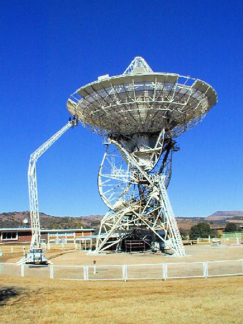
The Hi-ranger is shown above seen from a distance.
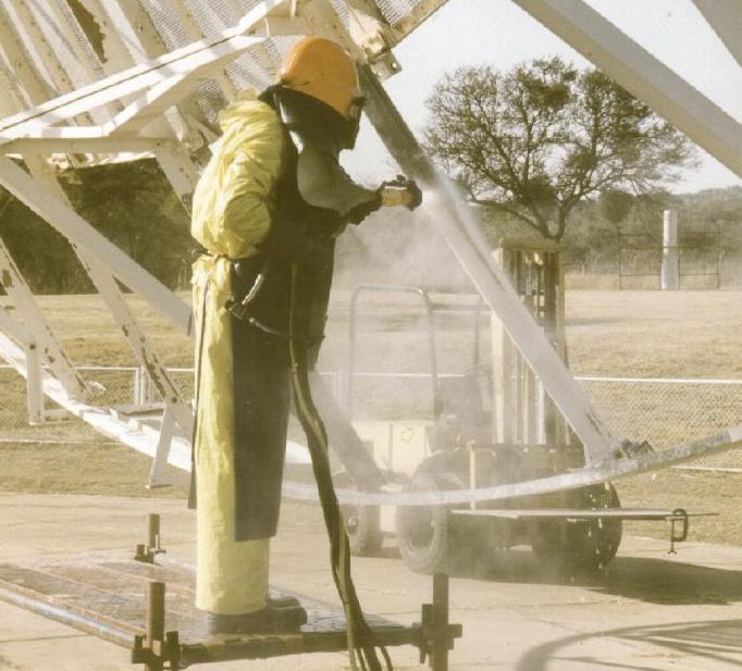
The surface structure is cleaned and repainted after removing the panels. Amos Kekae is seen above using a dry powder spray of sodium bicarbonate to remove the paint.
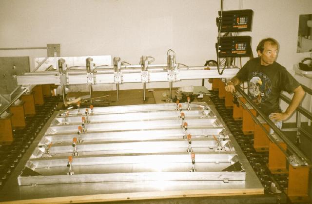
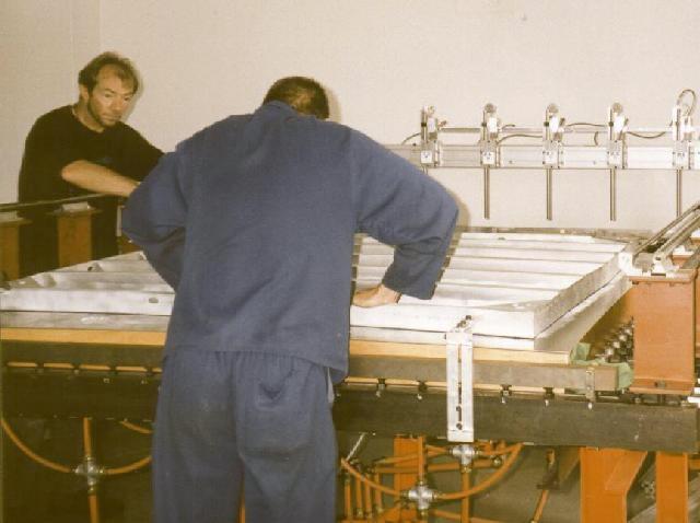
The new surface panels for the 26-m Hartbeesthoek telescope make use of the old frames which previously carried a perforated plate surface. For each frame the old surface panel is unscrewed, the three existing ribs are cut out, and a sodium bicarbonate powder spray is used to strip the remaining paint. Five new ribs are then welded into the frame while it is supported on the "bed of bolts" that sets the surface curvature of the panel, as shown above. Bruce Cross provides the scale for the frame. Holes are then drilled in the frame for securing the surface after attaching it with resin.
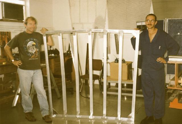
The picture above shows the frame with the new ribs welded in, supported by Bruce Cross and Jacques Grobler.
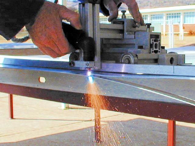
A thermal arc plasma cutting torch (Thermal Dynamics model PCH/M-28) is shown above being used by Bruce Cross to cut the aluminium panels to size. To make a straight cut, the torch is mounted on a trolley that runs on rails. In the torch a pilot electric arc heats and ionizes the air, which has been compressed to 4.8 Bar. The plasma temperature is 6000 Celcius, and it can cut through 12mm of material.
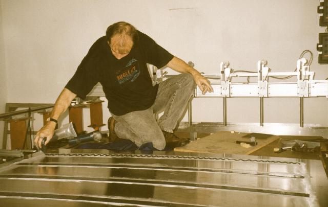
Bruce Cross is seen above applying resin to the new solid surface panel. The panel is being held down on the "bed of bolts" by a vacuum system to force it to the correct curvature.
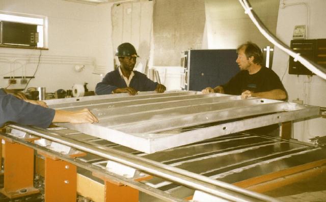
The frame is shown above being lowered onto the resined panel by Jacques Grobler, Simon Morake, Amos Kekae and Bruce Cross.
The frame is pushed down onto the resin by Bruce Cross and Jacques Grobler.
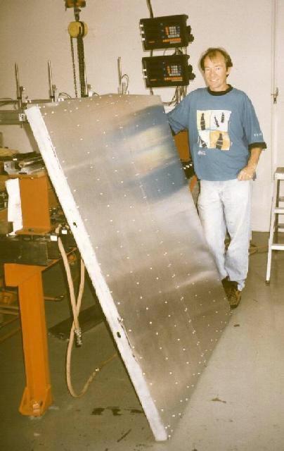
The resin takes about eight hours to set. The edges of the panel are then trimmed and the panel is screwed onto holes predrilled in the frame. The completed panel is shown above supported by Bruce Cross. The surface shape of the panel is then measured with electronic probes on a square grid at intervals of 10 cm. The accuracy of the height measurement at each point is about 15 microns.
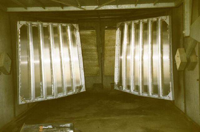
Before installation, batches of panels are spray painted matte white in a spraying shed. Two panels are seen hanging in the shed before painting.
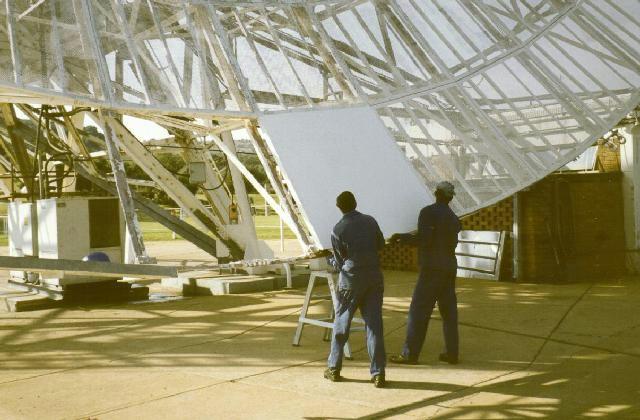
The installation of the first panel of a batch of five in April 2000 is shown above, as Simon Morake and Amos Kekae move the panel into place.

Here Jacques Grobler, Simon Morake and Amos Kekae manouever the panel into position.