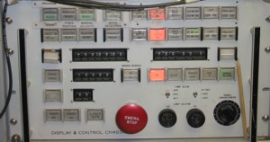
Az/El Display and Control Chassis #1.
The MOBLAS 6 ranging system tracks the target and positions the receive telescope assembly to receive the expected return pulse from the target. The following page discuss target tracking and mount positioning in greater detail.
Basics. Based on a predicted laser pulse return time calculated by the Controller Computer, a time frame or interval known as a window is established for the expected receive pulse. In order to eliminate unwanted noise and false readings, the MCP-PMT and the receive discriminator are gated on only during the window period. This variable window width is preset from 200 nanoseconds to 51 microseconds (in 200 nanosecond increments) on the computer, and output to the LRC chassis. The LRC chassis gates the MCP-PMT and receive discriminator on to begin the window. The range word opens the range gate (window) , one half its width early. The window counts down from its selected width to 0. At 0, the window and gate close.
Returning from the target, the reflected laser pulse is detected by the MCP-PMT in the receive telescope assembly. The receive pulse is applied to receive discriminator through Delay Box. The receive discriminator produces a trigger signal for the LRC logic circuits and the stop pulse to halt range TIC . The Delay Box also provides the receive pulse to the input of Oscilloscope, Channel 1. Another output of the delay box is applied to the input of the receive integrator, which then supplies a relative energy measurement to CAMAC.
Range. Channel 3 of Oscilloscope is used in conjunction with channel 1 to analyze the receive pulse. When the range TIC receives the stop pulse, it supplies the range (elapsed time) to the Controller computer. The controller computer performs the dual roles of calculating the azimuth and elevation signals required to drive the tracking mount to the correct position, and formatting and recording the ranging data for each ranging operation.
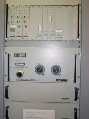
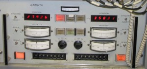
Positioning Signals. The azimuth and elevation positioning signals are applied to T&MC subsystem servo interfaces. The source of azimuth and elevation positional data (synchro or encoder) is selected at Display and Control Chassis No. 1. The positional data is displayed at both Display and Control Chassis NO.1 and the operator control box. The T&MC subsystem allows alignment of the transmit and receive optics, and positions the optics in accordance with commands from the controller computer for ranging operations. Mount Positioning And Control System (MPACS) readout chassis in the T&MC subsystem is a signal conditioning system that processes the inductosyn inputs. The readout chassis generates corresponding azimuth and elevation angle information for display on Display and Control Chassis NO.1. Servo Control Chassis receives inputs from the controller computer, the inductosyn assemblies, and generates the corresponding drive signals to position the mount.
Structure. The T&MC subsystem consists of:
![]() tracking pedestal;
tracking pedestal;
![]() optical equipment;
optical equipment;
![]() control circuitry.
control circuitry.
The function of the T&MC subsystem is to acquire and accurately track spacecraft during laser ranging operations. The mount control servo system and controller computer are used to aim the tracking pedestal.
The tracking pedestal consists of an optical mount housing supported by three leveling legs. The leveling legs make the tracking pedestal self-supporting and free from van vibration by isolating it from the MOM van. The optical mount housing supports the following equipment:
![]() operator control box;
operator control box;
![]() laser beam expander;
laser beam expander;
The azimuth axis housing contains a preloaded thrust bearing to support the mount weight. The elevation axis housings also contain preloaded angular contact bearings that maintain an orthogonal relationship between the azimuth and elevation axes. Each axis housing contains slip ring assemblies for all control wiring.
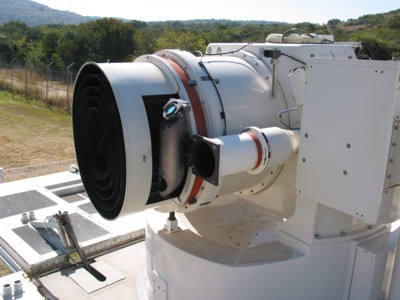
Receive optics. The receive optics consists of a 76.2-cm (30-inch) Cassegrain telescope and a photomultiplier tube. The telescope is contained in an aluminum housing. The telescope front and rear windows seal the unit. The primary reflector is an f:1.5 parabolic mirror. The secondary reflector is a hyperbolic mirror which, together with the primary reflector, provides an f:5 system. The primary baffle is mounted to the primary mirror center support post. The baffle shields extraneous light from the MCP-PMT.
The main detector assembly is mounted behind the receive telescope main housing. It has 2 ports: one MCP-PMT port, and one CCD camera port. The eyepiece is inserted into the MCP-PMT port for performing star calibrations. The detector assembly contains the MCP-PMT, the field of view iris assembly, the visual optic assembly, and the sun shutter. All are mounted in a carriage subassembly that moves in order to focus the telescope. The field of view iris assembly is located in front of the MCP-PMT. This motor-driven assembly controls the MCP-PMT field of view. The visual optic assembly (eyepiece) permits viewing of the received image. To protect the MCP-PMT from the direct rays of the sun, a solenoid-operated sun shutter covers the assembly. The spring-loaded sun shutter also covers the MCP-PMT when the power is off. Applying power retracts the shutter until the sun sensor detects increased sunlight caused by mount movement toward the sun. When the mount moves to within 10 degrees of direct line of sight with the sun, the shutter closes. When the mount moves at least 10 degrees away from this direct line of sight with the sun, the sun shutter uncovers the MCP-PMT for normal operation.
To allow tracking inside 10 degrees from the sun, a sun baffle is fitted to the front of the receive optics. Consisting of a series of concentric metal rings, it reduces the angle of solar acceptance into the telescope to approximately 10 degrees off axis. This helps minimize the risk of either injury or equipment damage that could arise from stray solar reflections.
Transmit Optics. The transmit optics directs a laser beam from the clean room to the mount, and through the transmit telescope exit window. The optics consists of five remote-controlled diagonal mirror assemblies, and the coude mirror drive control box. The five adjustable mirrors are mounted in a coude optical path. All mirror assemblies in the path are identical. Each is adjusted by connecting the coude mirror drive control box to the external connector of the mirror assembly being aligned. The mirrors can be tilted by actuating the correct combination of three driver stepper motors. These mirrors are adjusted (controlled) only during alignment procedures. For normal operation, they are stationary.
Each mirror reflects the laser beam in a different direction along the coude optical path. Mirrors A and 8 align the laser beam on the laser table so that the coude mirrors can route it through the transmit optics assembly. Mirror 1 receives the laser beam. from mirror 8 and directs it upward along the mount vertical axis. Mirror 2 reflects the laser beam horizontally to mirror 3. Mirror 3 directs the beam vertically to mirror 4. Mirror 4 directs the beam horizontally (along elevation axis) to mirror 5. Mirror 5 reflects it along a path parallel to the receive telescope axis and out of the transmit optics assembly.
Sighting Telescope. The sighting telescope is a 127-mm (5-inch) f:10 Schmidt-Cassegrain reflector. It uses an illuminated reticle, and provides an erect image in the right-angle eyepiece. It is used by the mount operator to position the receive telescope for tracking or collimation. Since the receive telescope defines the optical mount axis, the sighting telescope is adjusted for initial collimation with the receive telescope.
Ranging Translator. The transmit and receive optics axes are separated by about half a meter. Because of the physical distance between the transmit and receive optics, optical parallax becomes an inhibiting factor in close-in ranging calibration. At ranges closer than 150 meters, it effectively prevents ranging. The ranging translator eliminates this problem by displacing the receive beam 28.845 cm (11.75 inches) toward the receive axis. Permanently mounted to the receive telescope, it swings into and out of both optical paths to allow close-in ranging. Once properly aligned, translator operation is transparent to the user; all correction factors are built into the ranging software. Figure 2-1 provides a simplified schematic diagram of the translator in operation. When in position, it puts a shaded beam splitter in the transmit path. Part of the transmit pulse is reflected to the shade, where it dissipates. The remainder of the pulse travels to the target, where it reflects back to the beam splitter. From the beam splitter, most of the pulse reflects to the mirror, where it enters the receive optics. The small part of the return pulse that passes through the beam splitter dissipates inside the laser table.
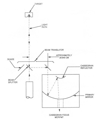
Figure 2-1: Ranging Translator simplified schematic diagram.
Servo Control Circuitry. The servo control circuitry controls tracking pedestal positioning. It functions in one of seven modes of operation. Selecting the program mode allows mount positioning control by the controller computer solely on the basis of programmed inputs. Selecting the fixed position mode allows execution of position commands set on the elevation and azimuth bias digital thumbwheel switches on Display and Control Chassis no. 1. Selecting the slave mode allows the subsystem to follow external synchro commands from a source external to the MOBLAS, independent of the controller computer. There are servo interface chassis which provide the interfacing connections for the controller computer to the servo system. MPACS readout chassis SA 1 is a modular signal conditioning system. It contains the electronics that process inductosyn signals and generate the azimuth and elevation angle information for displays.