
HartRAO Home > image gallery
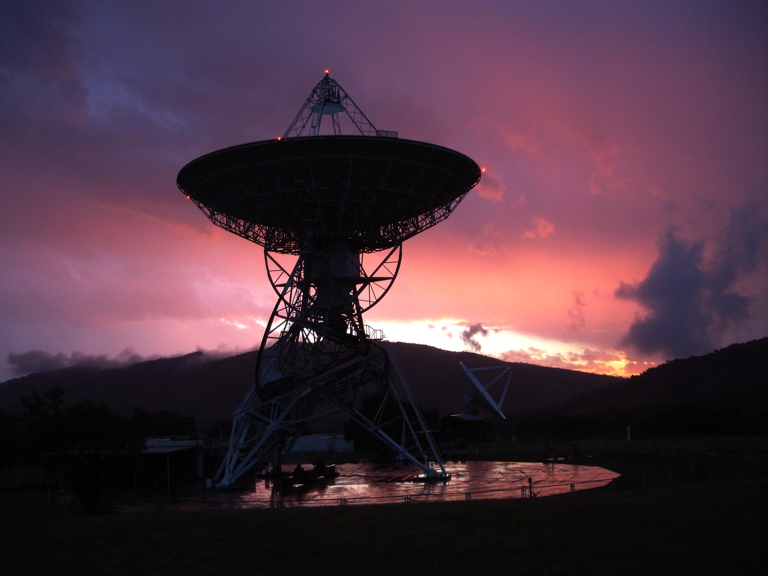
Pretty but deadly. The storm that produced this lovely sunset on 2013 April 3 also produced a lightning strike that blew various electronics and caused a 2 hour shutdown of VLBI R1579 while Keith Jones, Lerato Nkadimeng and Jon Quick repaired enough damage to resume operation - hence the 26m telescope parked at zenith in the picture. Credit for the photo opportunity goes to Jon, who noted the sunset while coming in from the rain.
The HartRAO 26m and 15m telescopes are seen above on 2012 September 11 during geodetic VLBI experiment R1551. The 15m was operating in tag along mode with the 26m, as part of commissioning test of the 15m telescope.

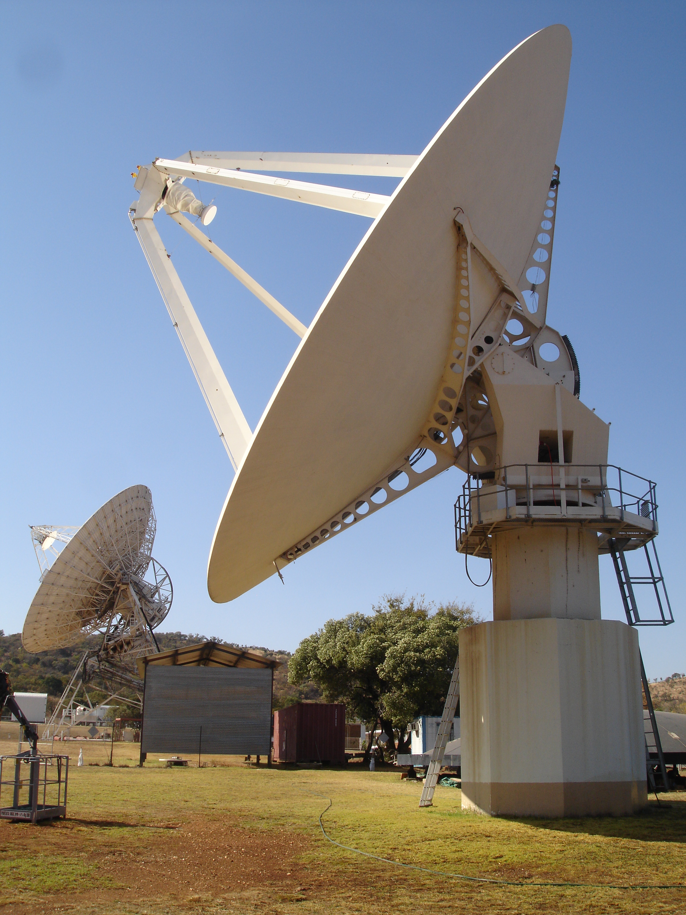
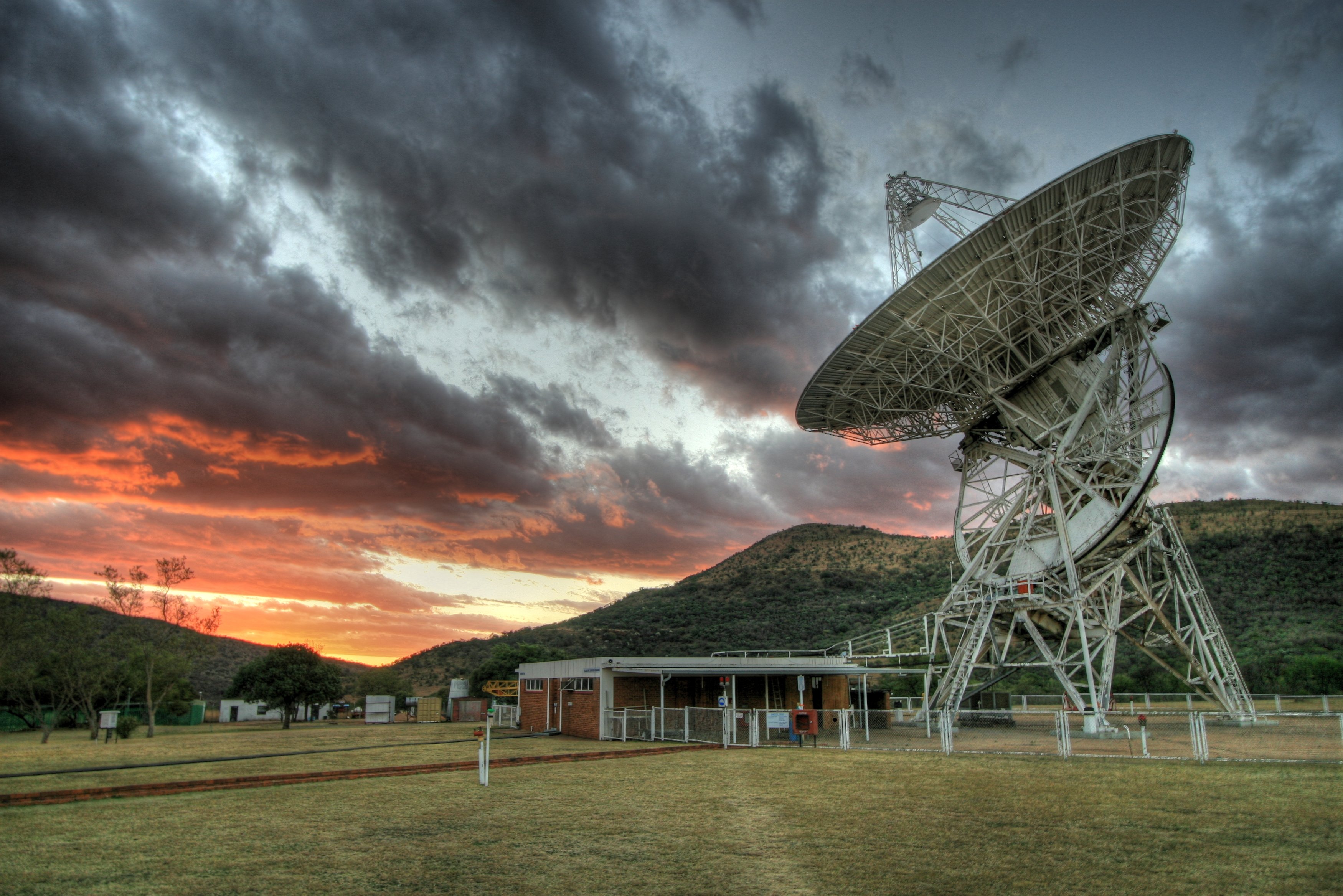
Testing the converted 15m telescope has been done by running it in parallel with the 26m telescope during gedoetic VLBI experiments. They are seen above operating together on 2012 July 17 during International VLBI Service experiment R1542.
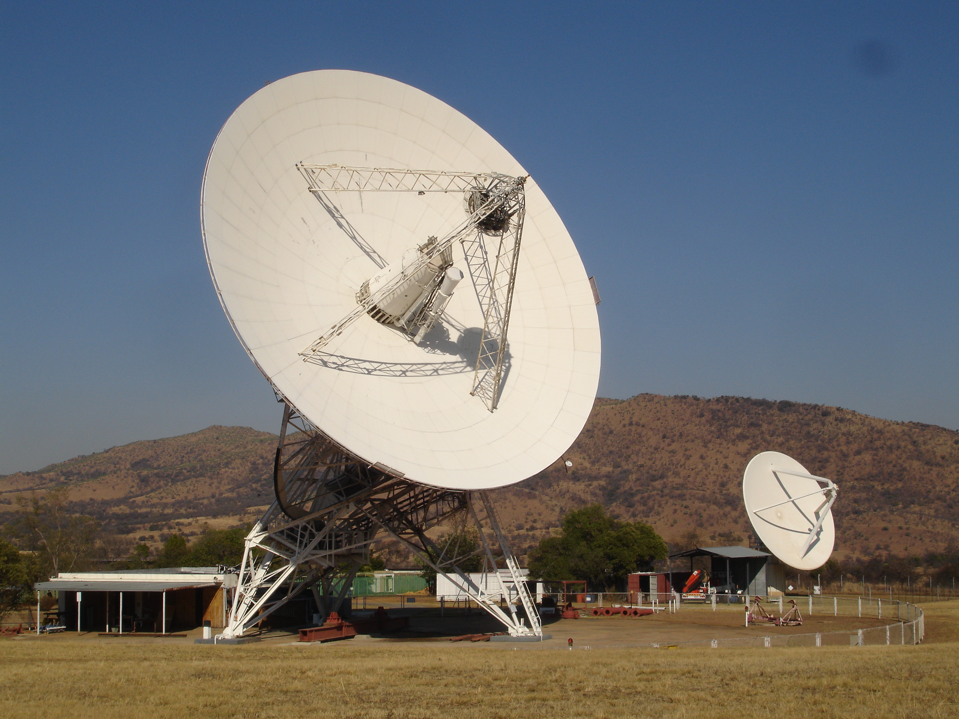
Taken on 2012 June 8, this image shows the 15 metre diameter radio telescope in the foreground and the 26m radio telescope in the background, both coincidentally observing the same source, the radio galaxy 3C123. The 15m telescope was built in 2007 as a proof of concept testbed for the Karoo Array Telescope. Its test programme having been completed, HartRAO built a new receiver for it operating at 2.3 and 8.4 GHz. This receiver was installed on 2012 March 30, and the picture was taken during commissioning tests. The receiver gives it an operational capability particularly for geodetic Very Long Baseline Interferometry (VLBI). This technique provides precise positions for the radio telescopes operating in the VLBI network. These in turn enable the changing rate of Earth rotation and rotation axis orientation to be measured very precisely, and on timescales of years measures the movement of the Earth's tectonic plates.

This image, taken on 2012 April 20, shows something unusual - the Satellite Laser Ranger at HartRAO is operating with a black cover over the telescope that receives the laser pulses reflected back from the satellite being tracked. The reason for this is that the satellite being tracked in this case was the NASA Lunar Reconnaissance Orbiter in orbit around the Moon. It is too far from Earth - about 400 000 km - to successfully reflect back the laser pulses, so instead it has an optical detector that picks up each pulse and sends a radio signal back to Earth. In this way, the distance from the HartRAO laser ranger to the LRO is measured with an accuracy of about 20 cm. The very successful LRO mission is perhaps best known publicly for the photographs it has taken of the Apollo landing sites on the Moon. In the background of the picture above, the 26m radio telescope is observing a source just above the Eastern horizon.

During the evening of 2008 August 29 a bush fire swept into the western part of the Hartebeesthoek valley. The 26m telescope is seen on the left, and the new 15m XDM telescope at centre, silhouetted against the flames and smoke.

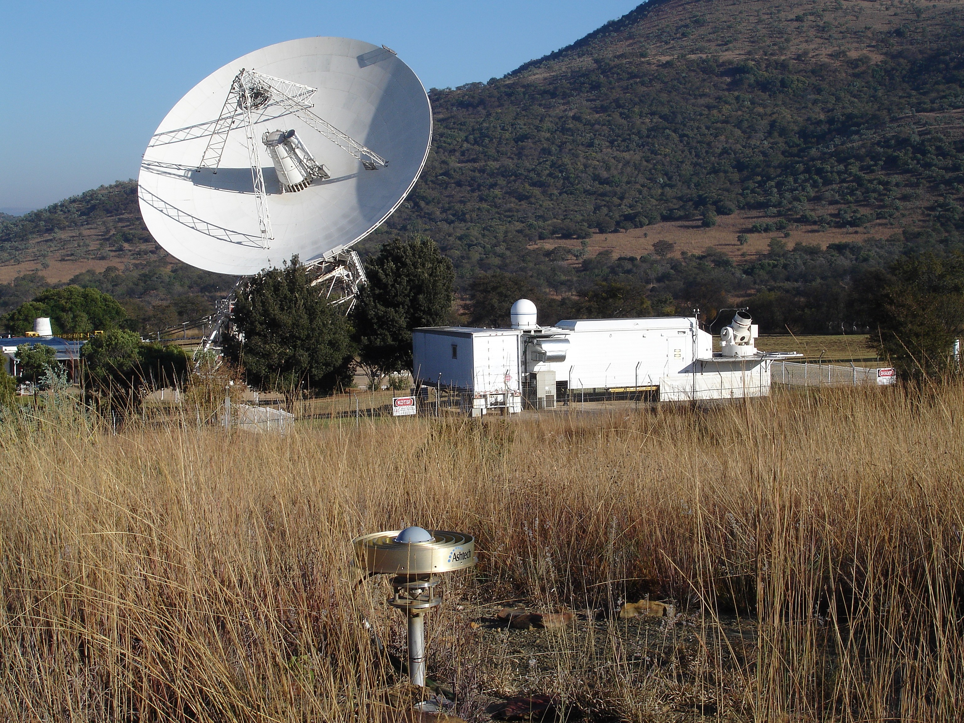
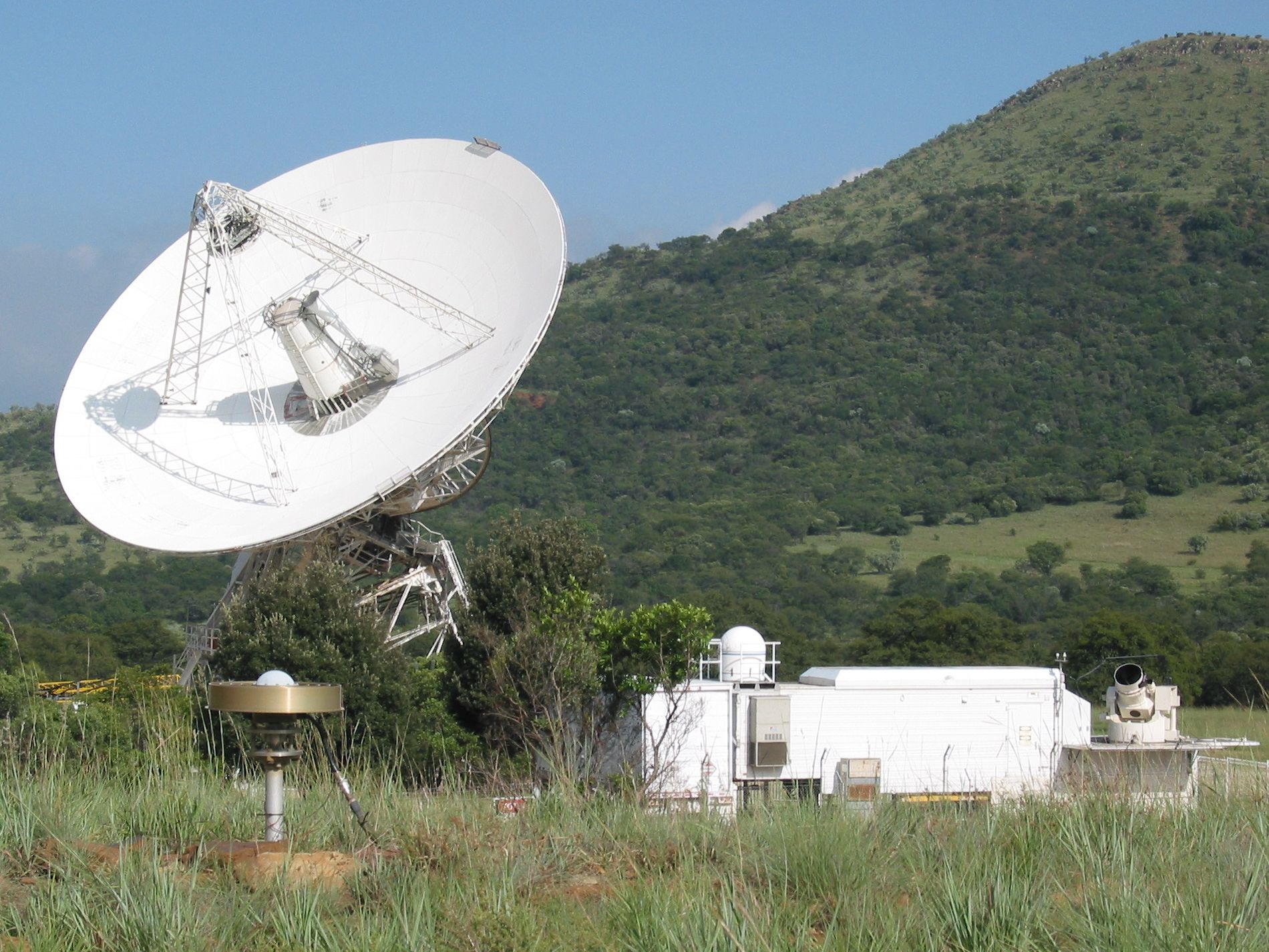
On 2008 August 15 the 26m telescope at centre is participating in CONT08 while to the left XDM is under test. The satellite laser ranger on the right is calibrating on a ground target. In the foreground the GPS basestation antenna runs continuously monitoring position and providing data for determining the amount of water vapour in the atmosphere and the total electron content of the ionosphere.
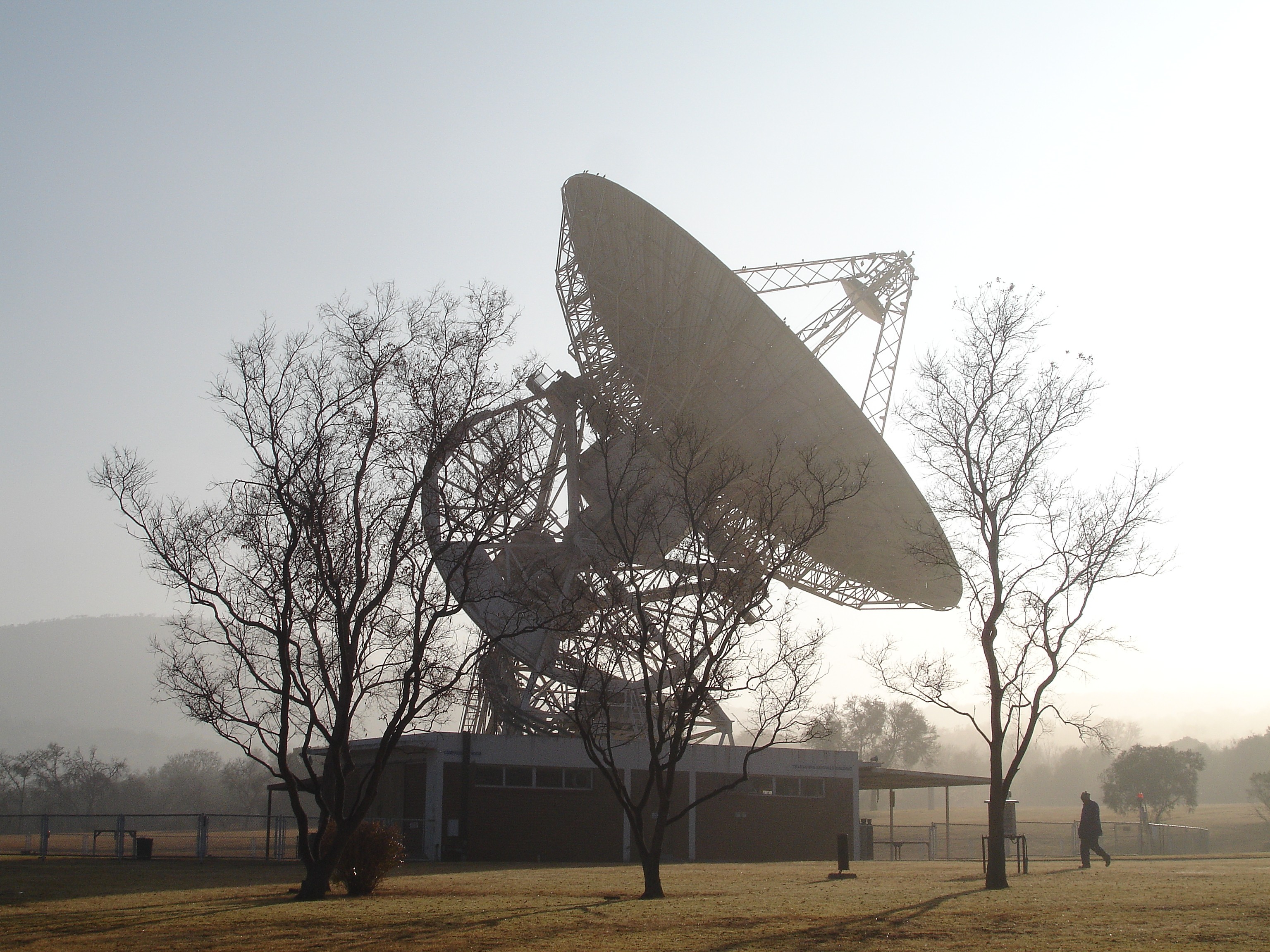
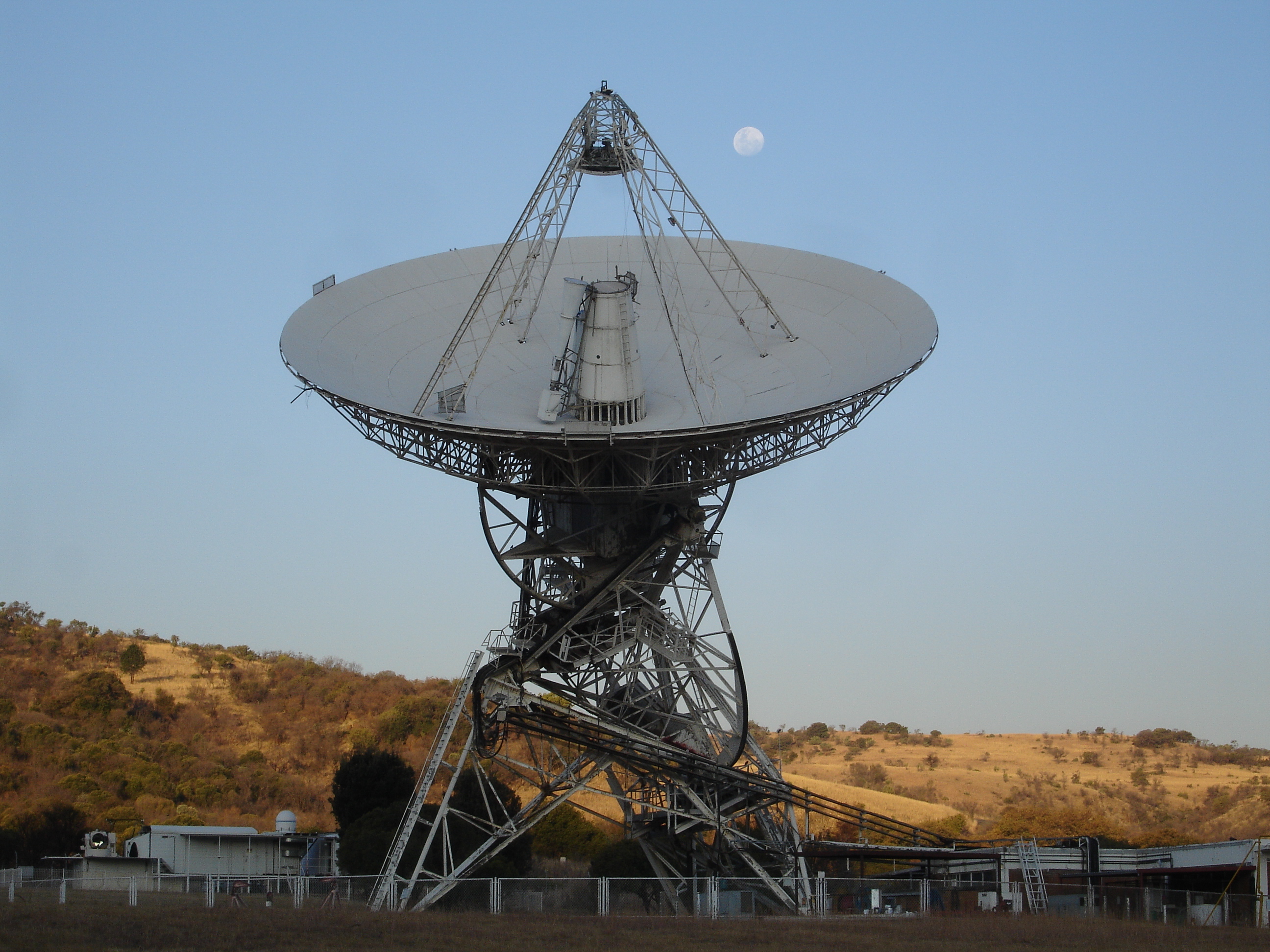
A misty winter morning provided this view of the 26m telescope at Hartebeesthoek. The telescope was observing pulsar PSR0736-40 at the time.
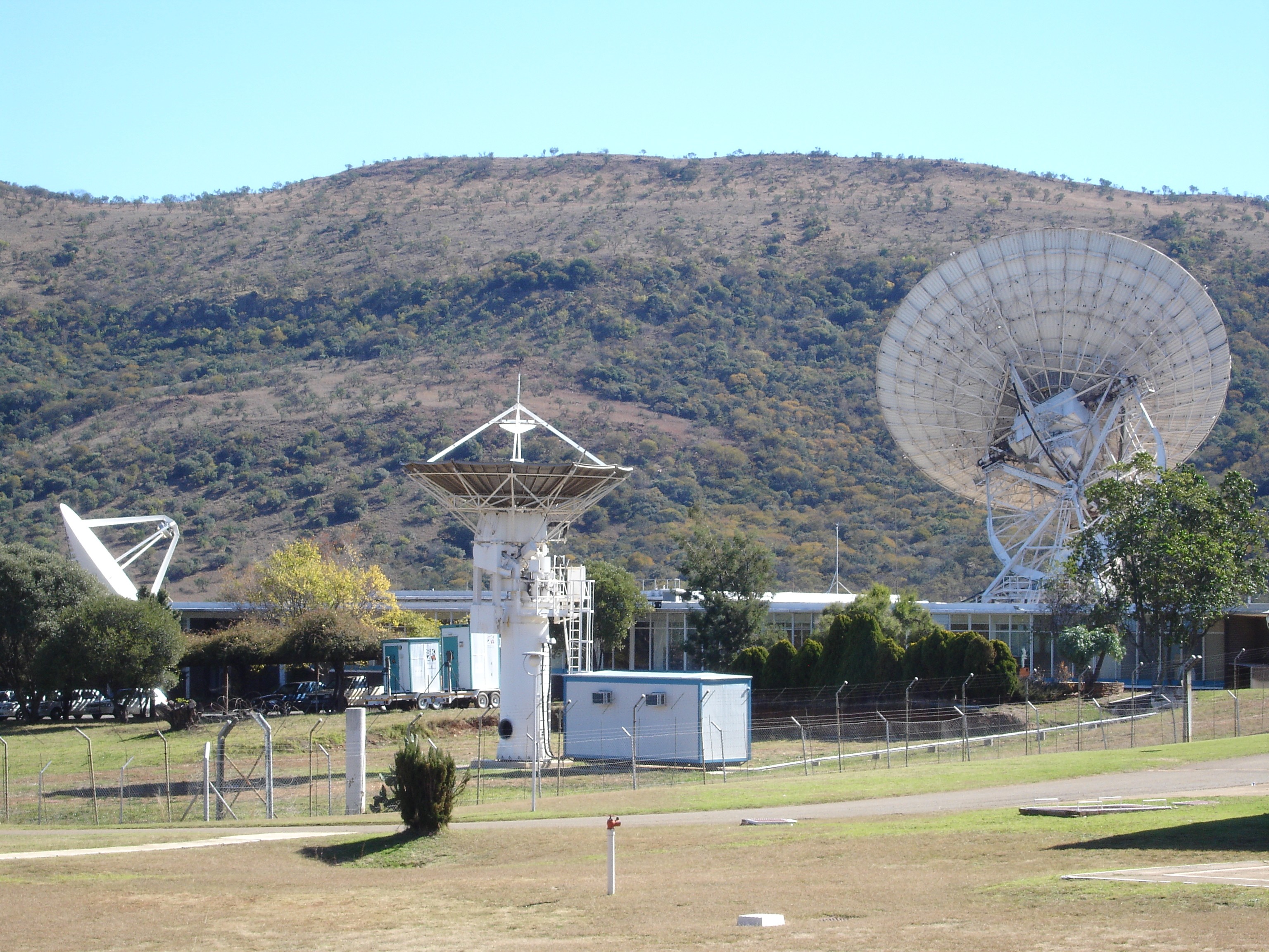
Three radio telescopes at HartRAO on 2008 June 6. On the left is the 15m diameter eXperimental Development Model (XDM) for the Karoo Array Telescope (KAT). Centre is the 7.5m antenna being converted to a telescope for the C-BASS project. On the right is the 26m telescope, which was operating as part of the European VLBI Network when the photo was taken.
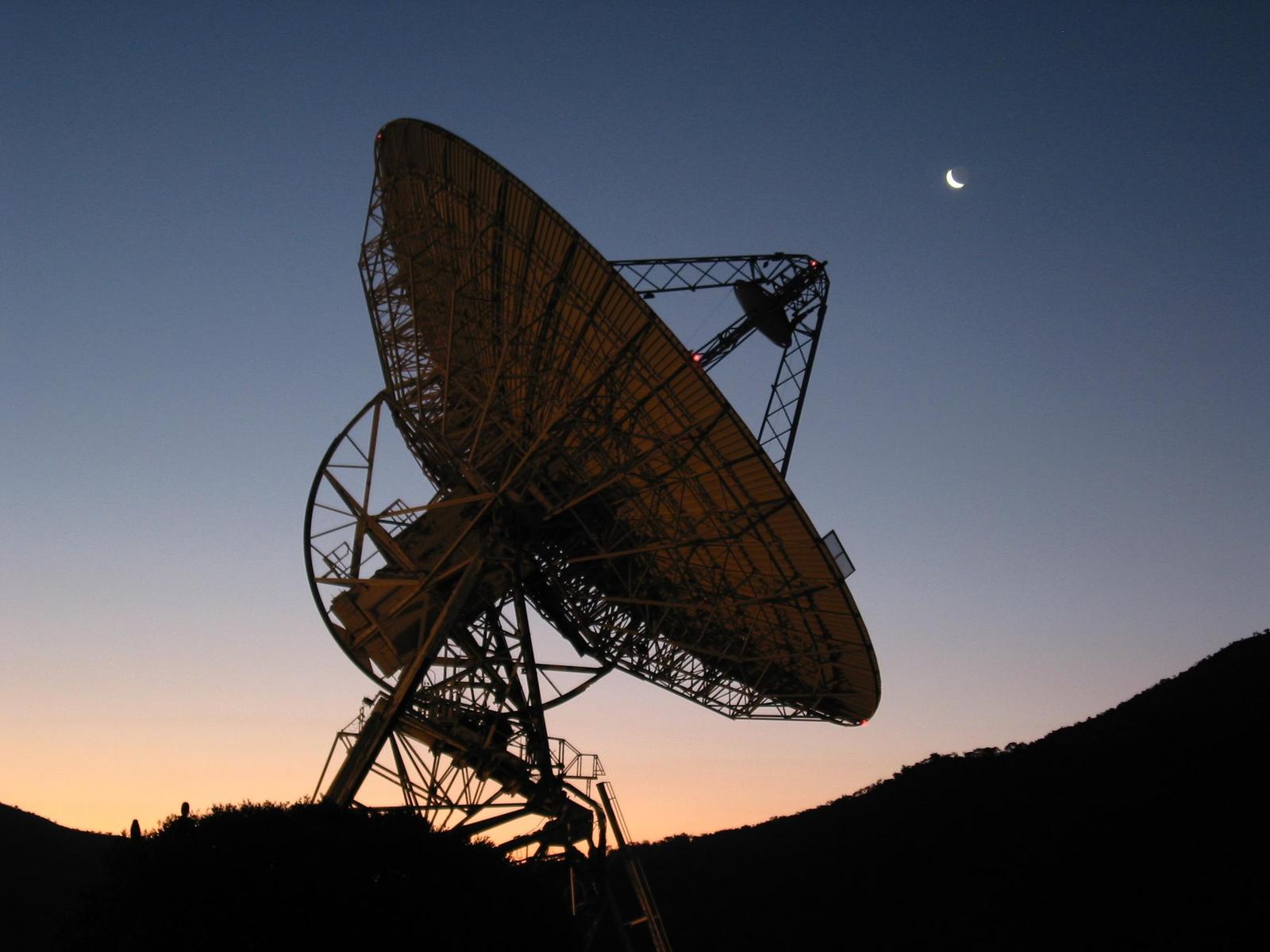
The rabbit and the dish. The Moon at phase 0.96 passes the 26m Hartebeesthoek radio telescope at sunset on 2007/06/28. The telescope is carrying out a calibration check using radio galaxy Hydra A. The full size photo clearly shows the "rabbit" on the face of the Moon.
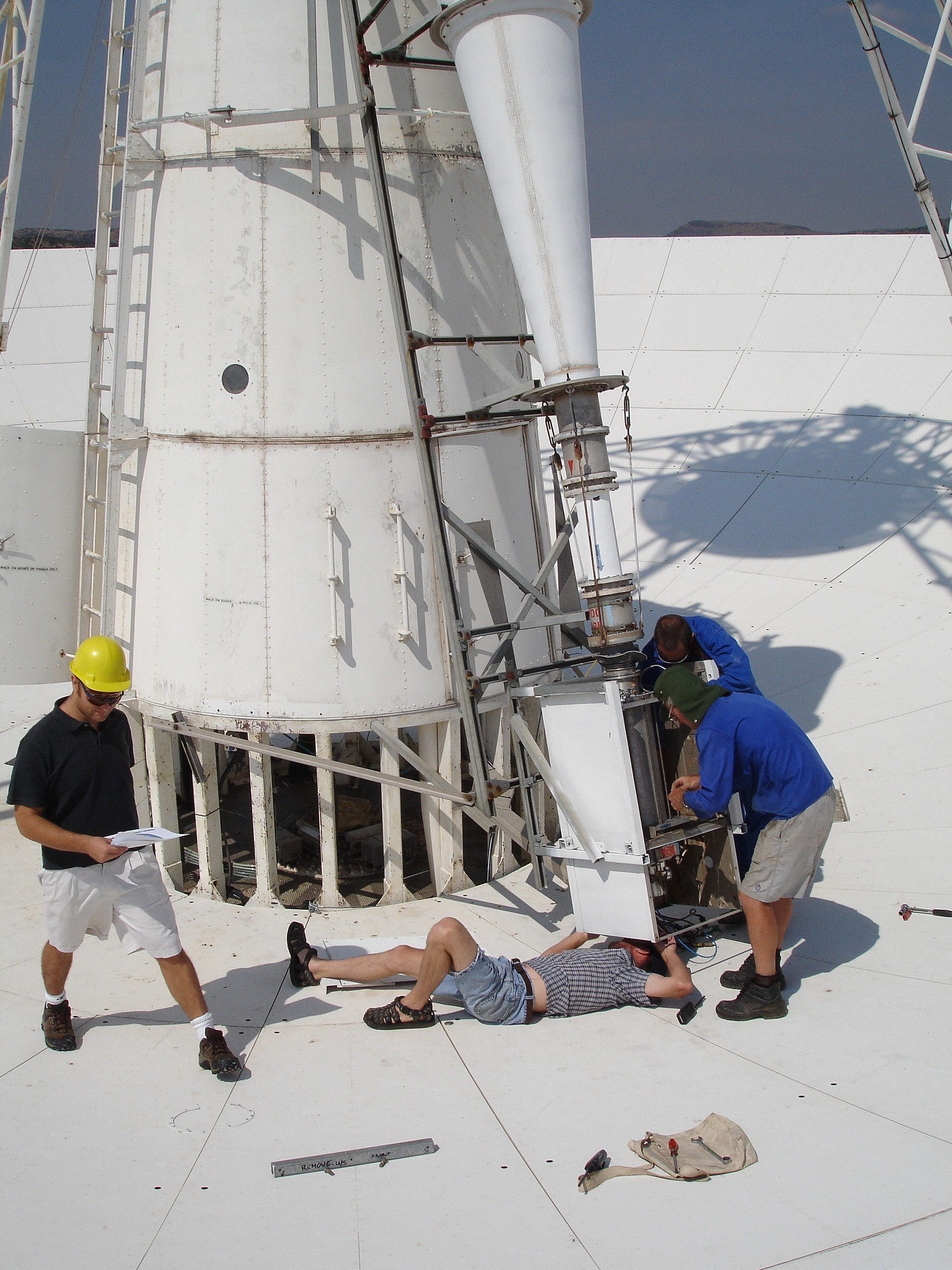
Installation of the receiver for 18cm wavelength on 2007/0/23 after testing on the ground. Pieter Stronkhorst, Attie van Wyk and Jacques Grobler reattach the receiver to the conical feed assembly above while minimising the time the cryogenic refrigerator that cools the receiver to -257C is disconnected.
University of the Witwatersrand MSc Engineering student Ben Klein is seen on the left comparing his map of the antenna surface panels obtained by microwave holography with the actual surface. The aim is to adjust the 252 panels to minimise the deviation from a perfect paraboloid.
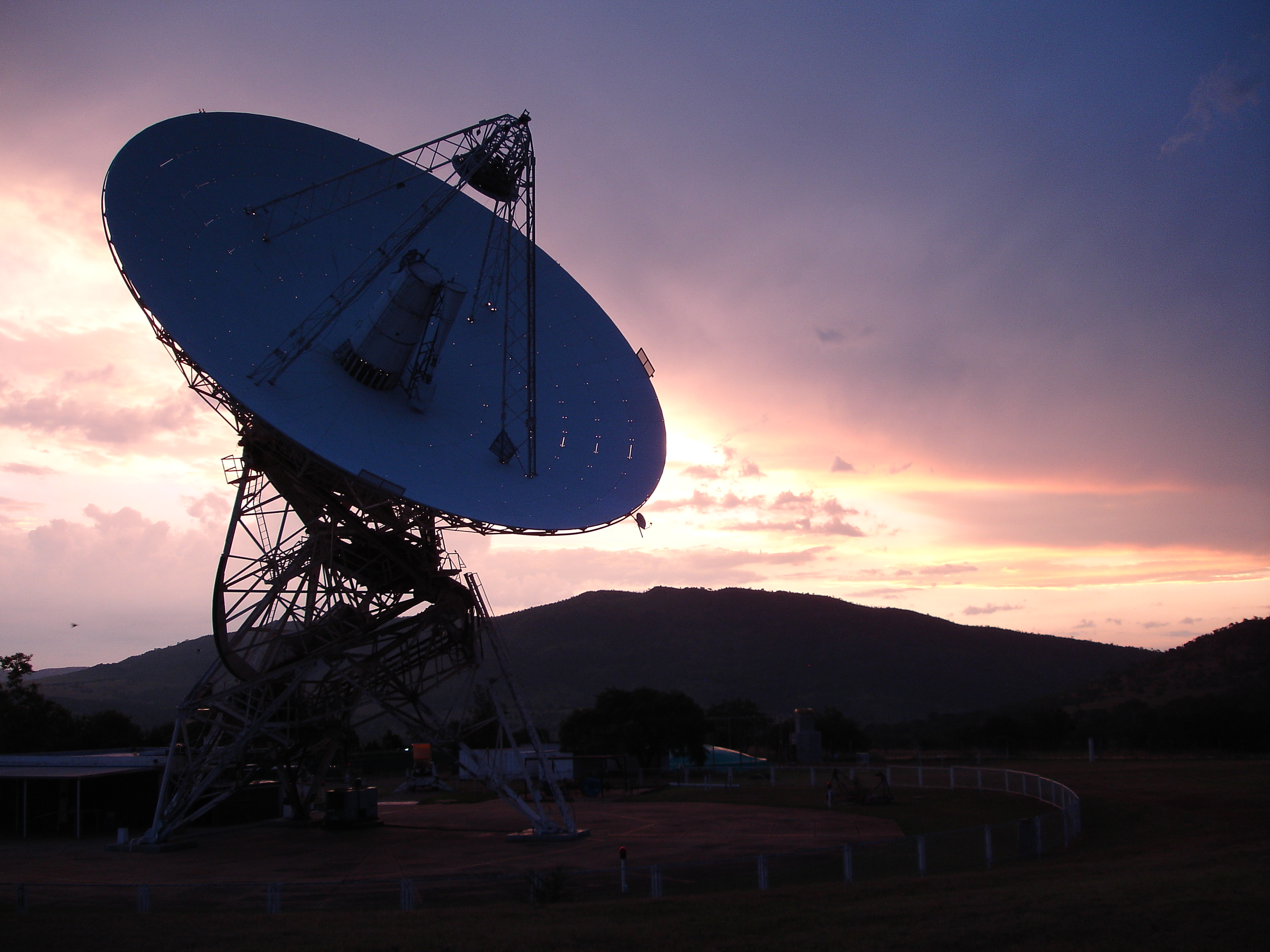
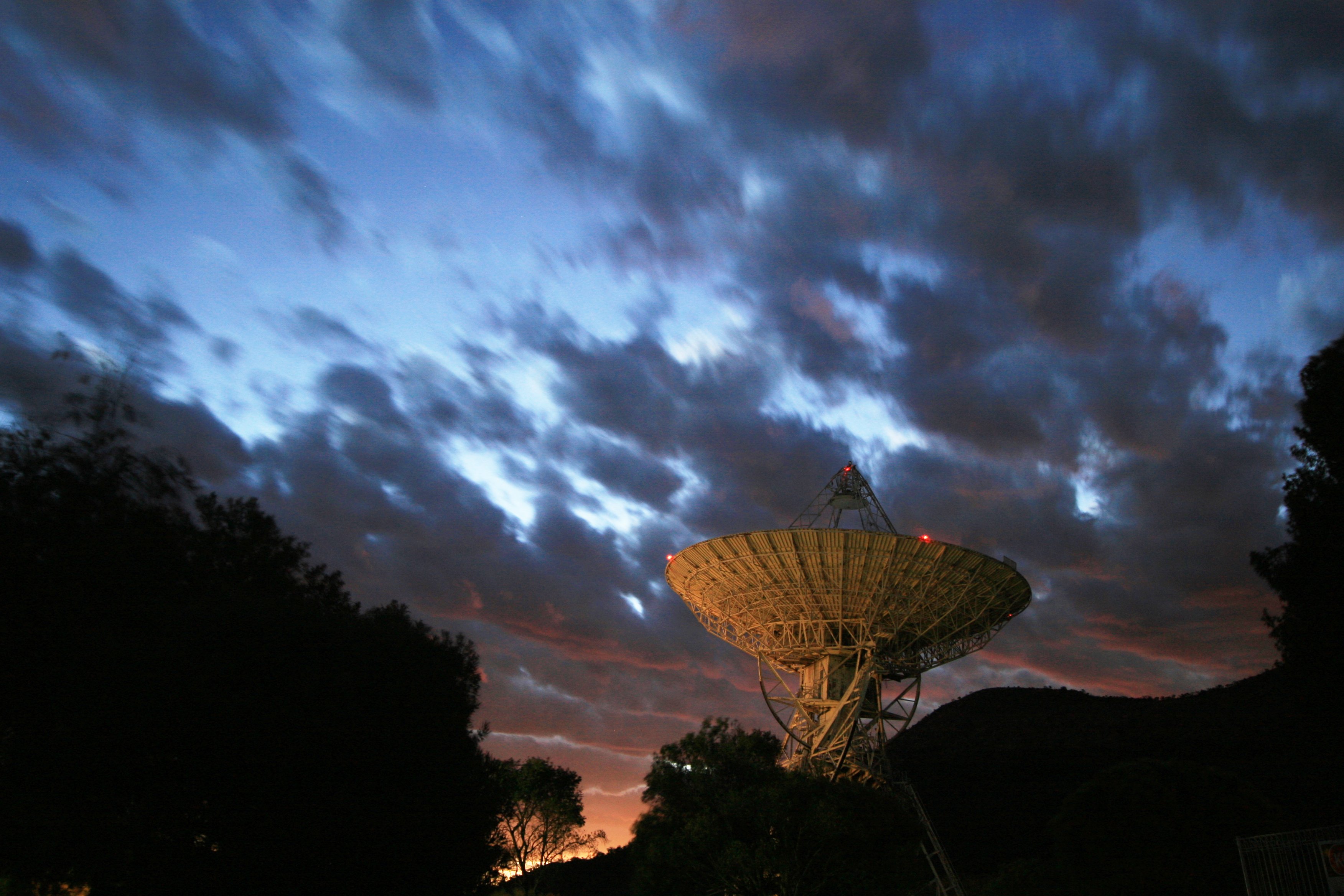
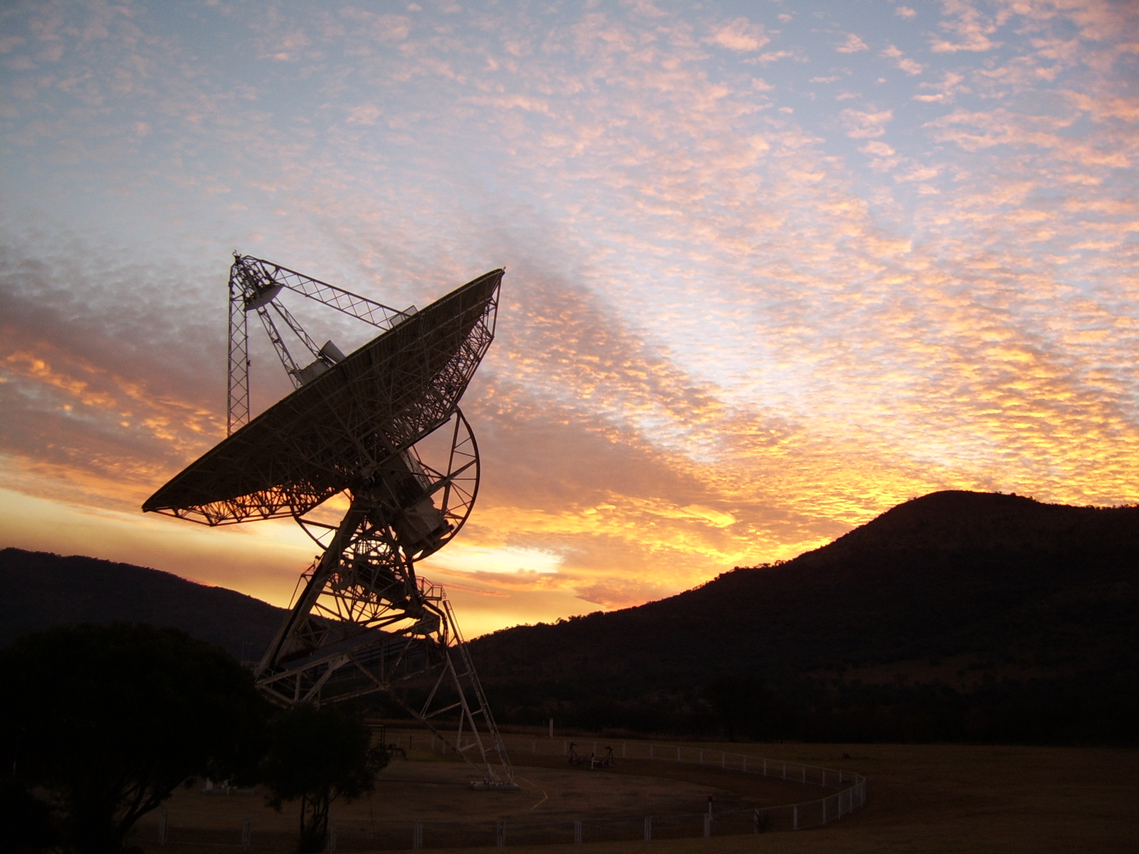
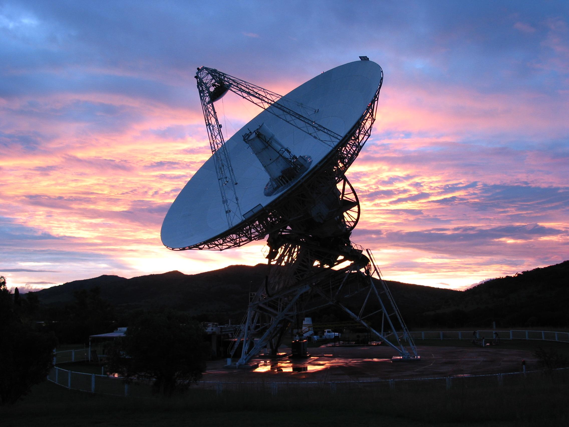
The stormy evening of 2007 February 17 provided this picture of the 26m Hartebeesthoek radio telescope.
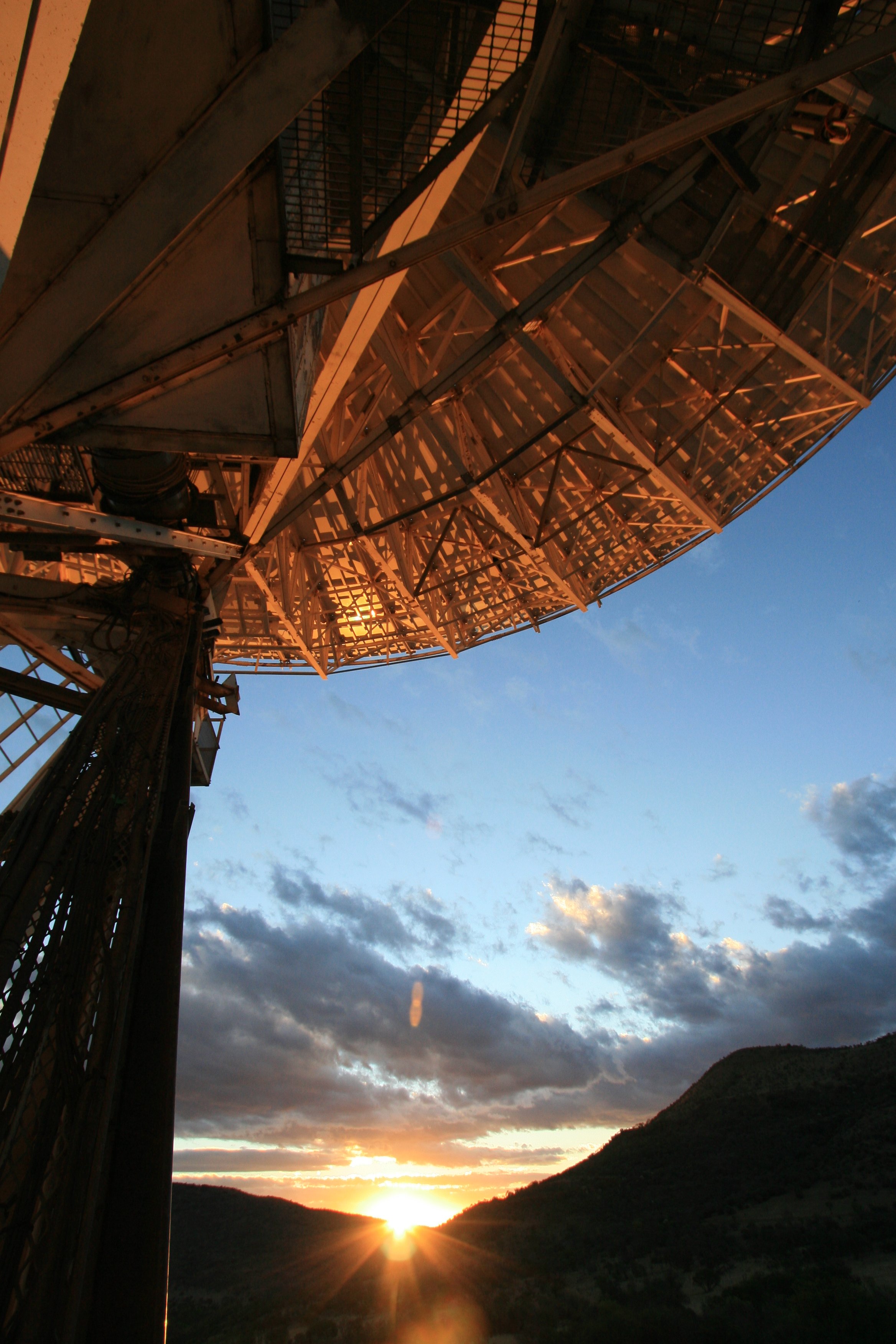
On 2006 September 17 visitor Thomas Abbott took some spectacular pictures as sunset approached and a cold front brought in some clouds.
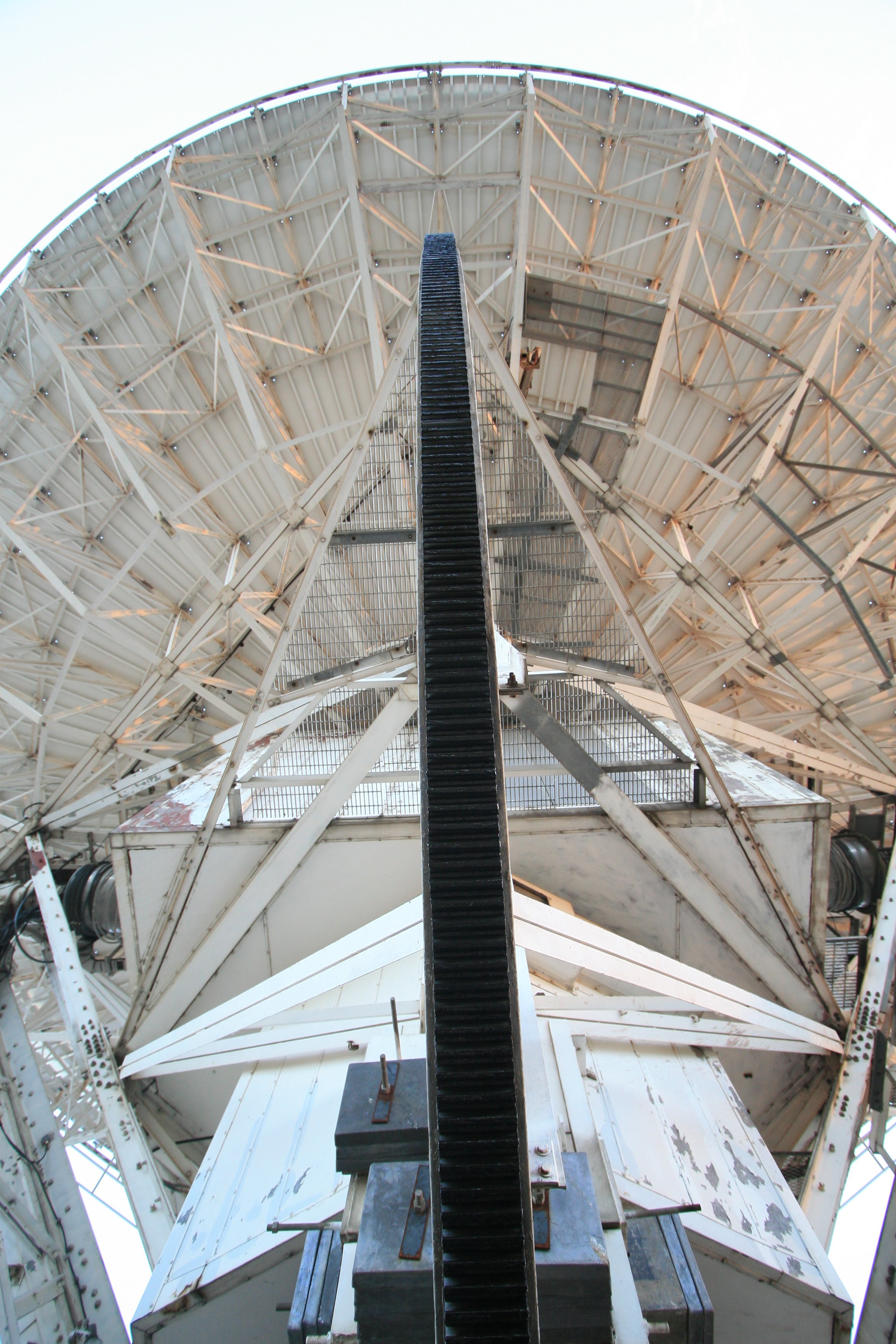
The black declination gear wheel dominates this picture.
The scudding clouds add drama to this picture.
The last of the sunset.
The 26m telescope at Hartbeesthoek was photographed on 2006 May 28 in the light of the sunset by Johan Bernhardt, the Manager of the Satellite Laser Ranger. Of course what looks pretty to us is a real problem for the SLR, which is trying to fire laser pulses at satellites far above the clouds, in order to measure their orbits.
Early morning at Hartebeesthoek on 2005 May 27. In the foreground is the small Global Positioning System (GPS) basestation antenna. Beyond the Satellite Laser Ranger prepares to measure the orbital path of a satellite, while the 26m radio telescope monitors the millisecond pulsar PSR0435-47.

Close up of the Satellite Laser Ranger at Hartebeesthoek early on 2005 May 27. The 26m radio telescope continues to monitor the millisecond pulsar PSR0435-47. Keen eyes will see the gibbous Moon near the top centre of the picture.
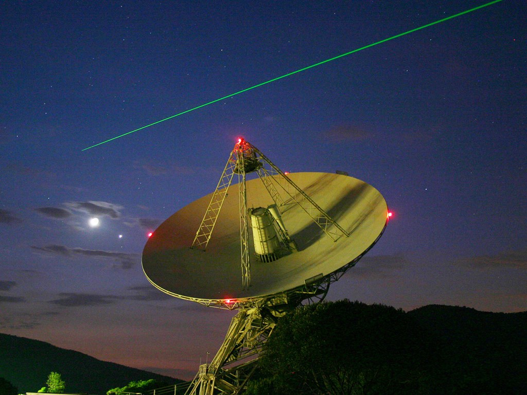
This picture was taken by a visitor during the public visit of 2004 January 25. The Moon and Venus lie just to the left of the radio telescope, while the beam of the Satellite Laser Ranger passes overhead.
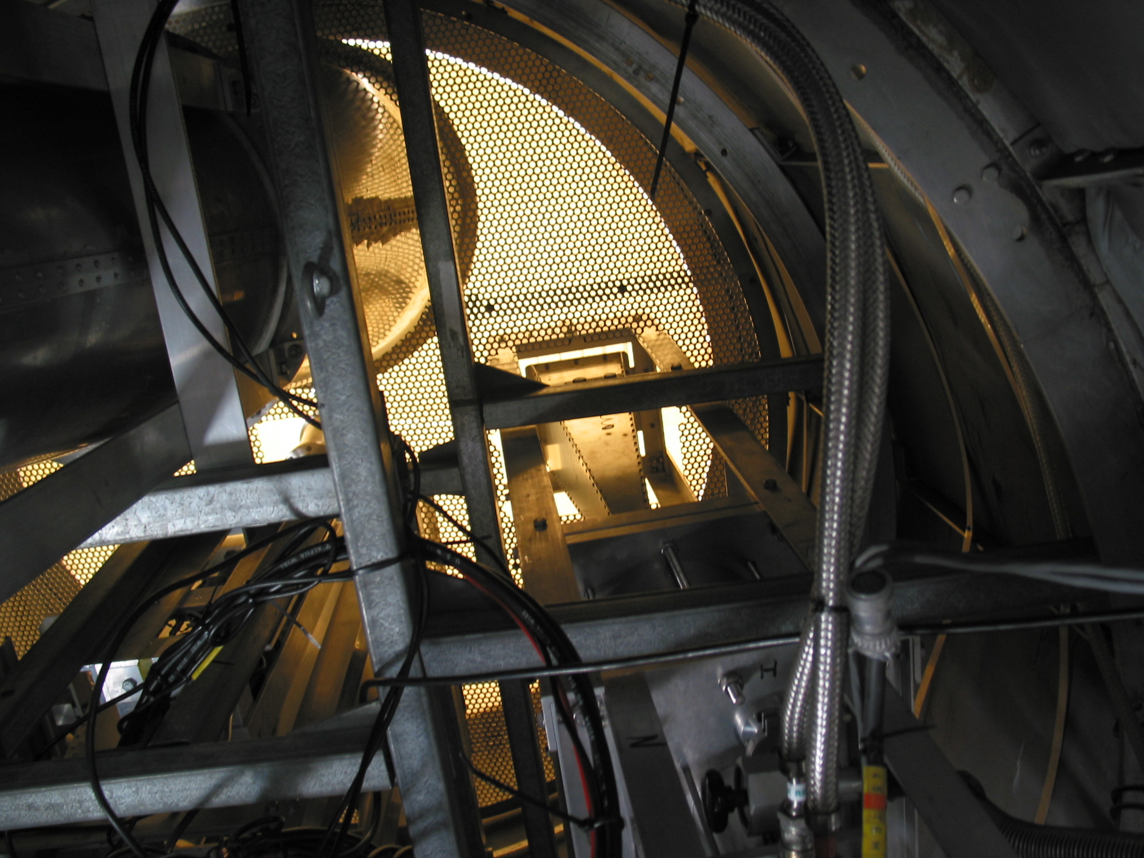
View of the microwave receivers inside the Cassegrain cone on the radio telescope. An orange light filters through the radome and reflects off the sides of the circular 13-cm wavelength feed horn on the left, and the rectangular 4.5-cm wavelength feedhorn in the centre. Image taken 2003/11/21.

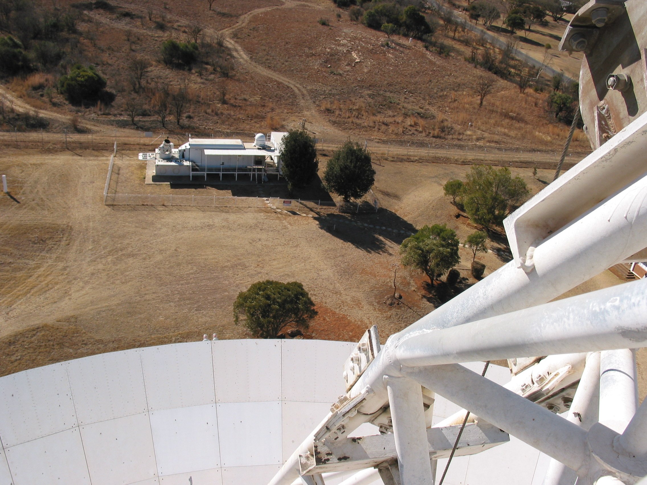
The presence of Director Justin Jonas (foreground) on the telescope to witness the installation of the last of the 252 new surface panels on 2003 September 10 provided another opportunity to photograph the Satellite Laser Ranger from the support structure for the hyperbola subreflector, at the very top of the telescope. At the SLR Louis Barendse (in the red shirt) and Johan Bernhard provide a human scale.
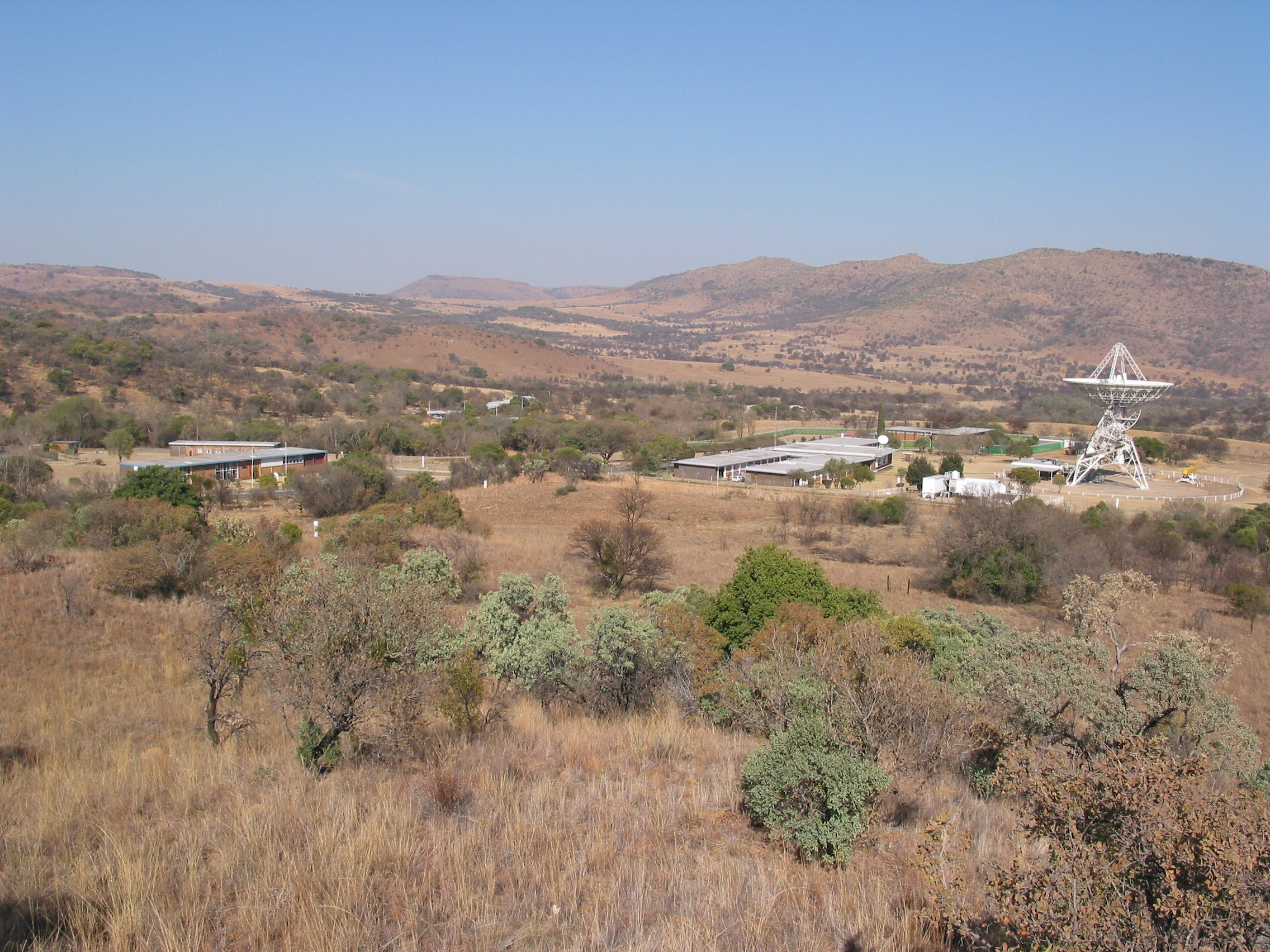
Panorama of HartRAO. On the left is the Visitors Centre, with the hostel visible over its roof. Just right of centre are the main control buildings. To their right is the bright white Satellite Laser Ranger followed by the 26m radio telescope. The very dry environment in Spring is evident. This was taken looking from the north-east on 2003 September 04.

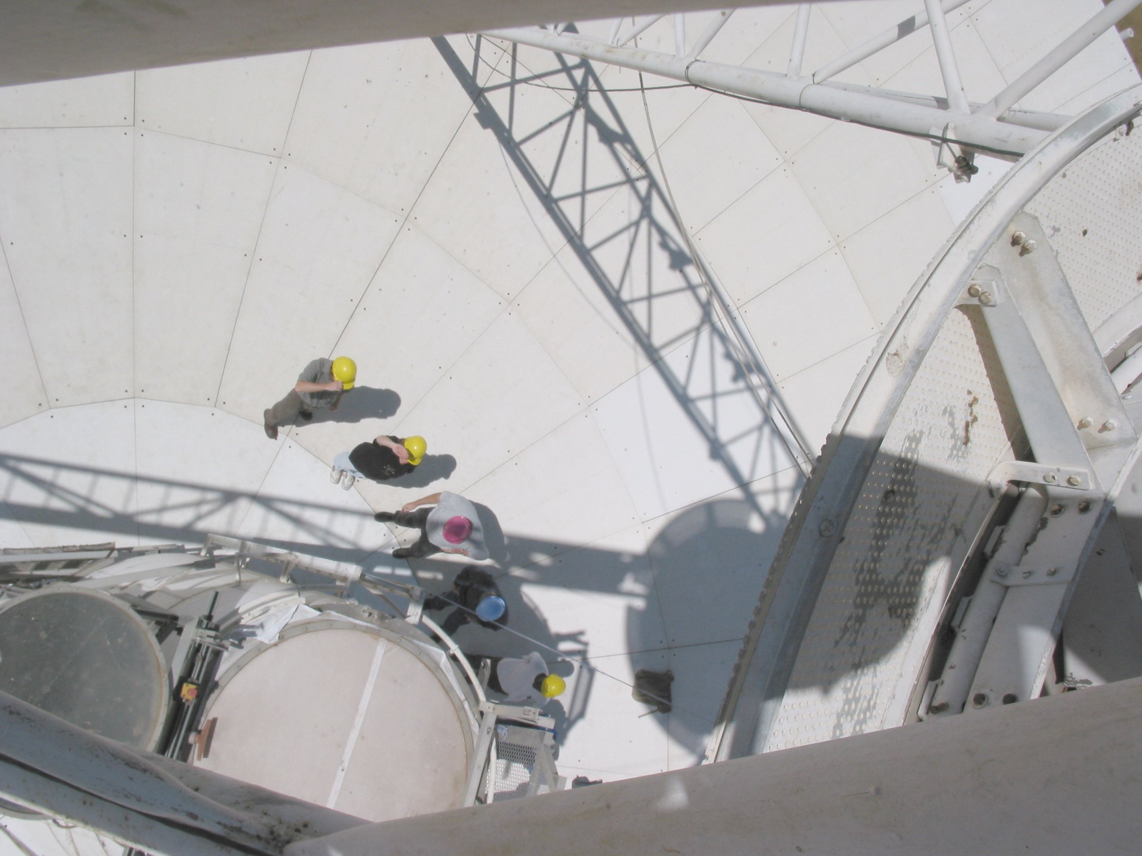
A trip up the radio telescope with the NASSP students on 2003 August 26 provided an opportunity to photograph the Satellite Laser Ranger from the support structure for the hyperbola subreflector, at the very top of the telescope. This point is 35 metres (115') above the ground. The panels of the main surface of the telescope are about 14 metres below the camera.
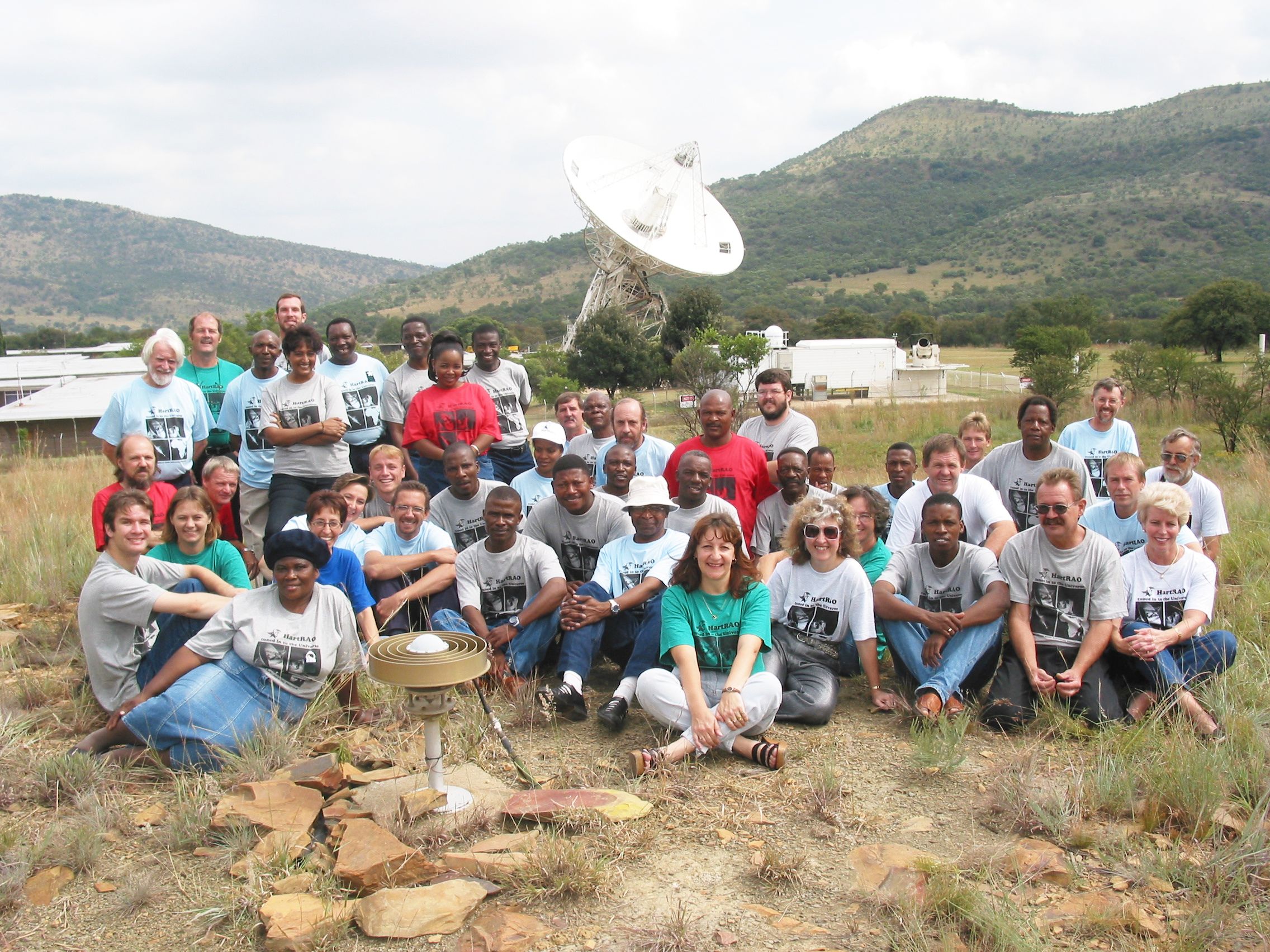
The operation of the observatory relies on its staff. Here they were photographed together for the first time ever, on 2003 April 14, the day of the farewell party for the retiring Director, Dr. George Nicolson, who is to be seen at the far left in the back row.
The Hartebeesthoek 26m radio telescope, Satellite Laser Ranger, and Global Positioning System antenna, pictured on 2003 March 07.
In the left foreground is the antenna of a Global Positioning System (GPS) receiver.
On the right in the middle distance are the two vans housing the MOBLAS-6 Satellite Laser Ranger (SLR). The laser ranger itself is mounted at the right end of the van and can be seen pointing up to the left - the large "drum" is the body of the telescope that receives the light reflected back by the satellite. The dome near the centre houses a radar system to track aircraft that may approach the path of the laser beam.
Beyond lies the 26 m radio telescope. All three systems are used in the Space Geodesy Programme at the Hartebeesthoek Radio Astronomy Observatory (HartRAO).
At the time this picture was taken, all but the innermost ring of the old main telescope surface of perforated panels had been replaced by more accurate, solid panels. The new surface permits operation at frequencies up to 24 GHz, doubling the usable frequency range of the telescope.
Sunset on 2003 March 3 revealed a lovely three day old Moon in the western sky. Coincidentally the angle of the radio telescope (observing a methanol maser in the Milky Way) matched the angle of the sunlit part of the Moon almost perfectly. The Earthshine on the dark side of the Moon has been nicely recorded, too - it is best seen in the full size picture. Well to the left of the Moon, comet C/2002 V1 (NEAT) could be seen clearly with binoculars.
As the rain cleared at sunset on 2003 February 20, the sunlit clouds provided an attractive backdrop to the radio telescope. The picture shows that the resurfacing of the telescope is almost complete, with only the innermost ring of panels still to be done. At this time the panel adjusters for the 250 new panels are being installed, in preparation for setting the panels to the correct parabloic shape. Picture by Mike Gaylard.
|
|
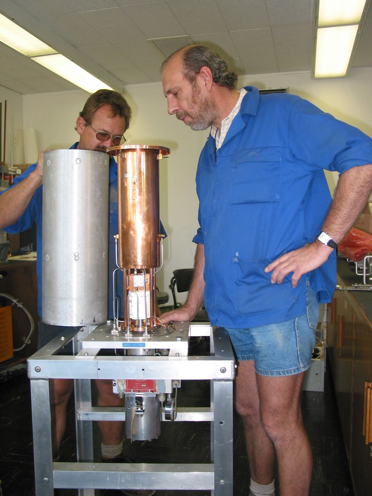
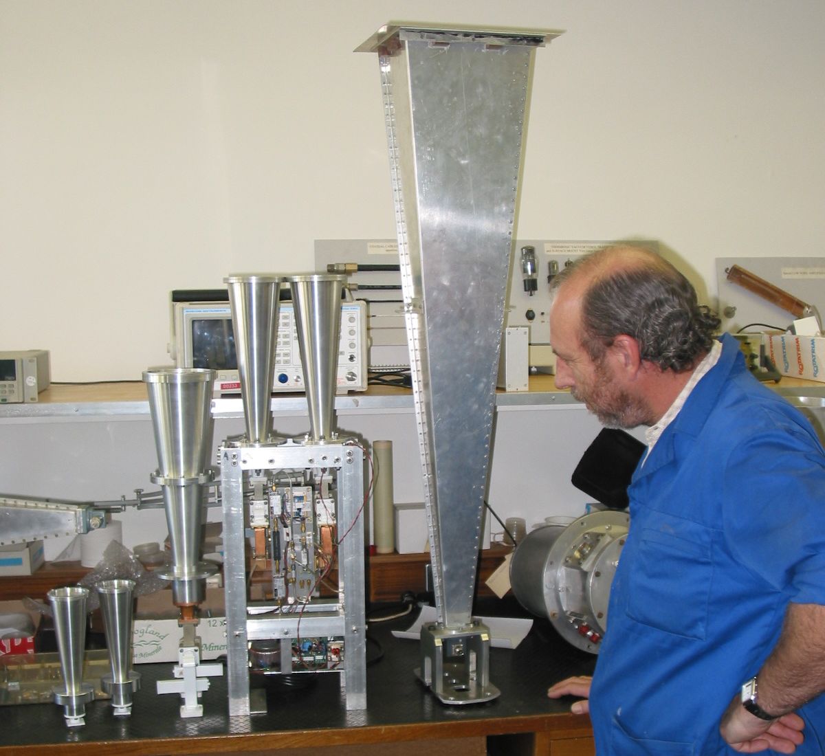
The image on the left shows the 18cm wavelength receiver when it was brought down from the telescope for a service in November 2002, providing a rare opportunity to see how it is put together. Mechanical technician Andre van der Merwe and microwave technician Johan Kriel prepare to re-assemble the receiver. Andre holds the aluminium vacuum jacket. Johan looks at the copper waveguide polarizer which attaches to the bottom end of the microwave feed horn. The polarizer has two probes which take the left- and right-circularly polarized signals via semi-rigid coaxial cable to the two amplifiers mounted below on the refrigerator. The refrigerator runs on helium gas and will cool them to 16 K (-257 Celcius) when in operation.
To take advantage of the upgraded surface of the radio telescope, new receivers are being constructed to operate at wavelengths down to 1.3 cm. The image on the right shows Johan inspecting, from the left, the two 1.3 cm microwave feed horns, the single 2.5 cm feedhorn that will provide dual polarization at that wavelength, the dual feed 2 cm wavelength receiver, and, for comparison, an older rectangular feed horn for 6 cm wavelength. The conical feed horns were turned by Rost Engineering in Centurion, with milling and final assembly by Andre van der Merwe.
|
|
|
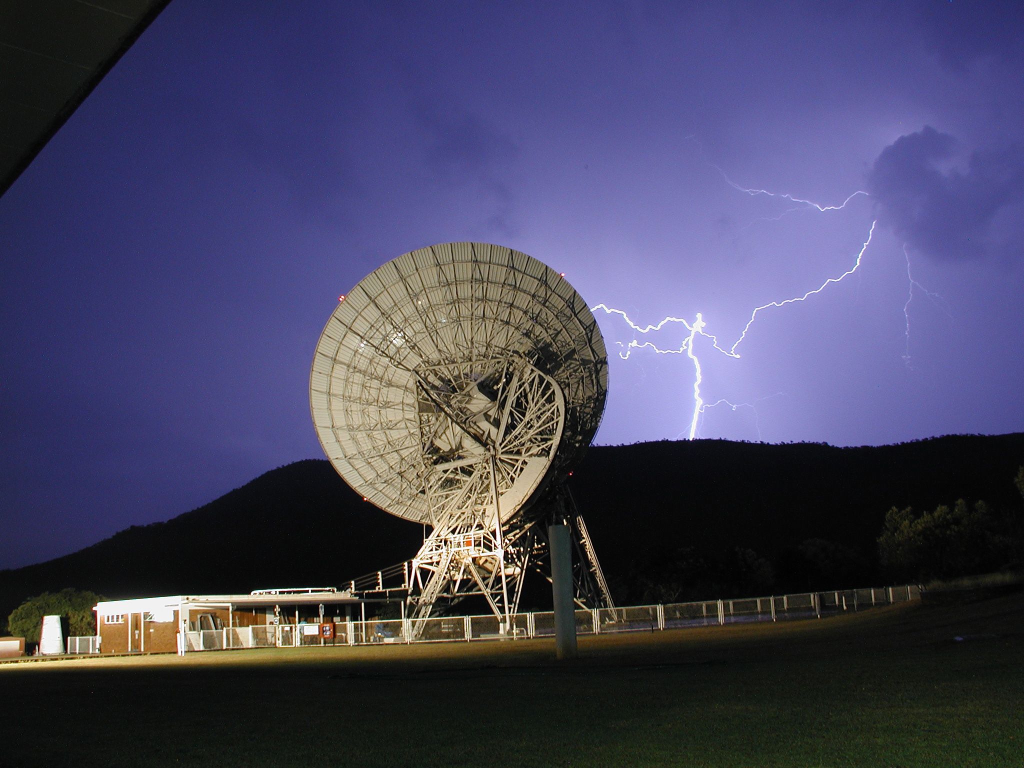
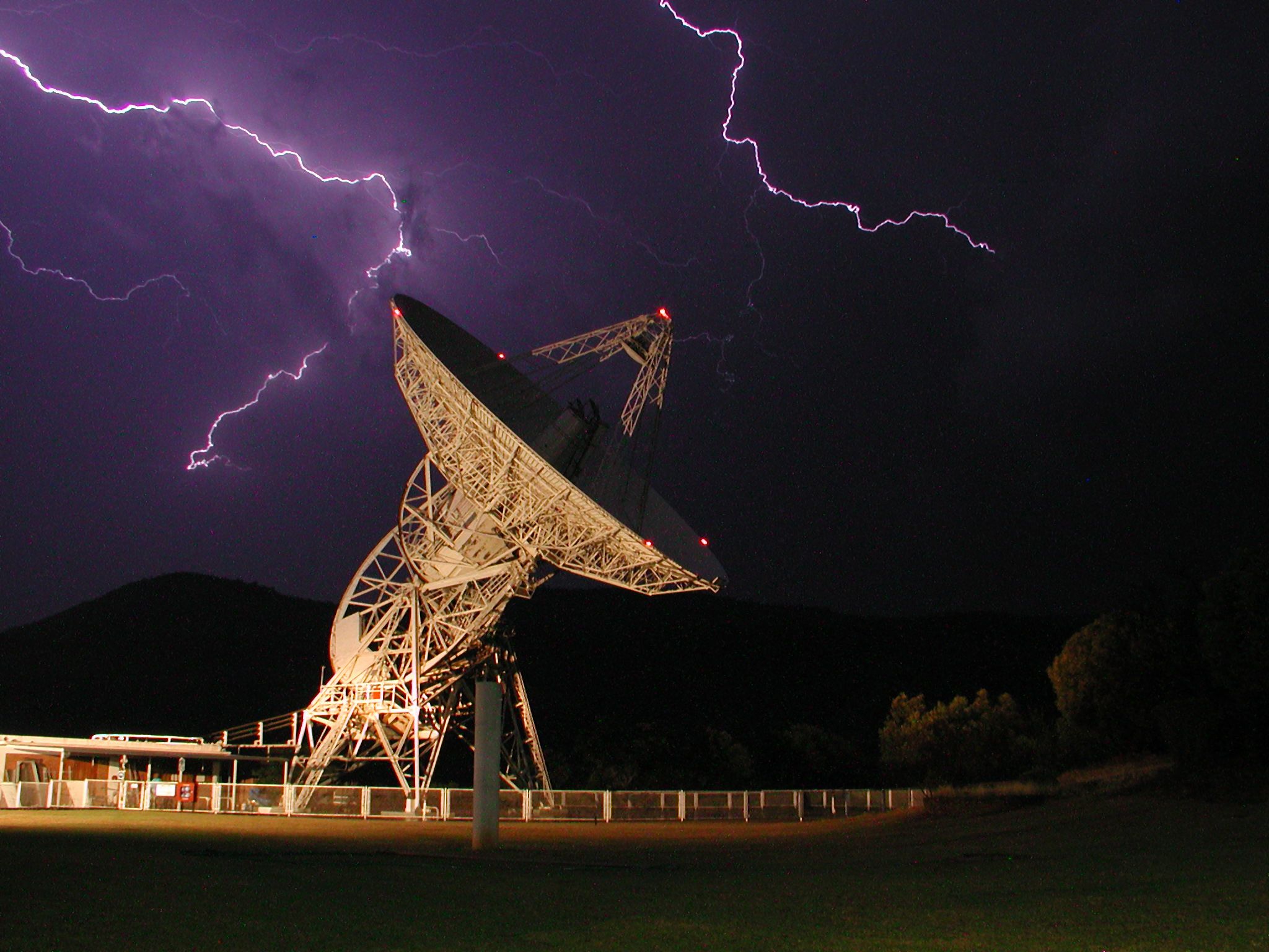
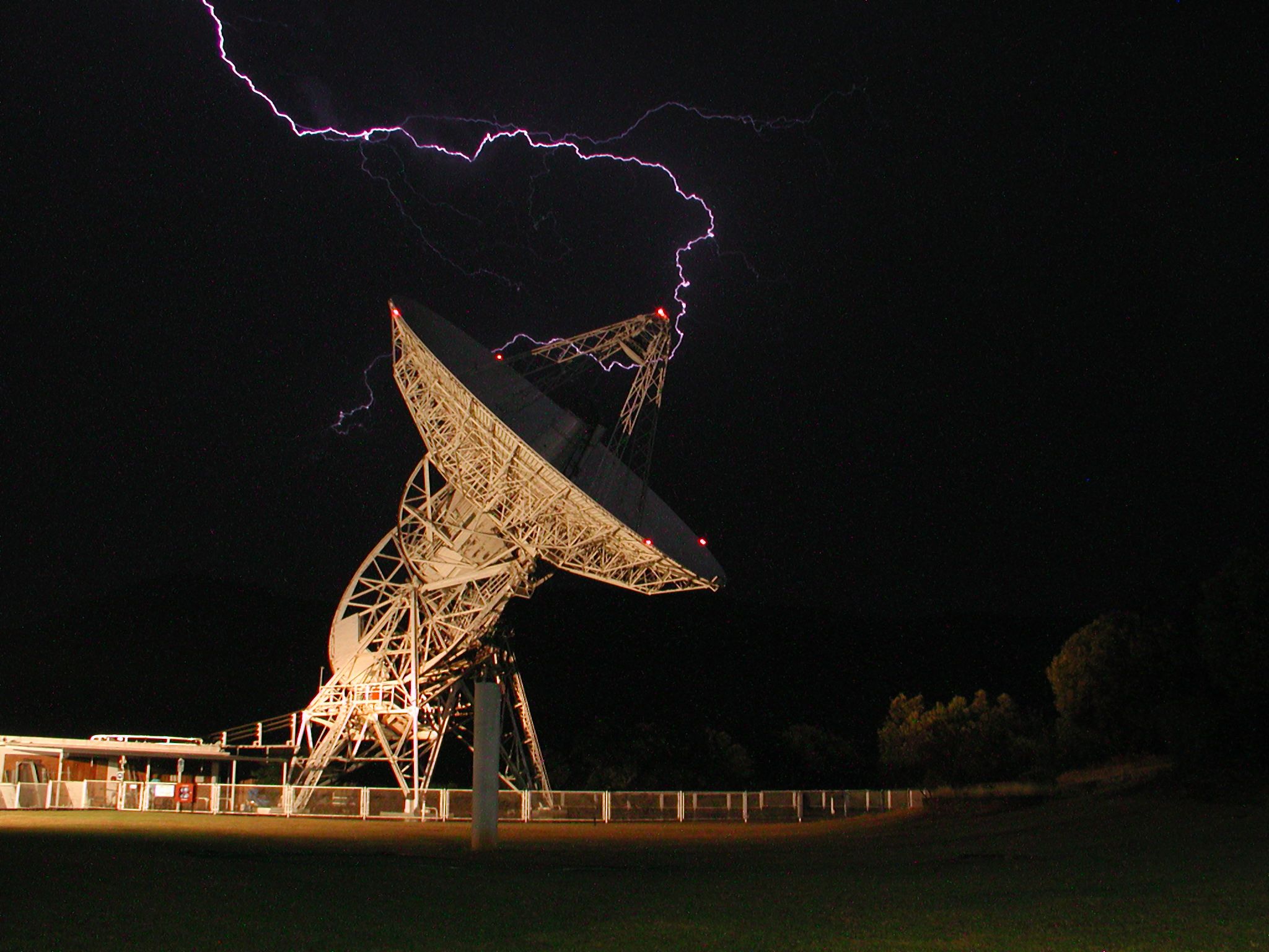
These dramatic pictures were taken during an electrical storm at HartRAO on 2002 October 23 by senior SLR operator Louis Barendse.

Fifteen Third Year Physics students from the University of the North West visited HartRAO with lecturer Thebe Medupe for a radio astronomy practical in 2002 October. Part of the experience was climbing the telescope to get a first hand feel for the antenna and its microwave receivers. The large "icecream cone" on the right is the 18 cm wavelength microwave feedhorn.